
ballbearian
Veteran Member
Well, at least he's still around...
Indeed. That's a good perspective.
Well, at least he's still around...

Very hopeful that tomorrow I get my rebored cylinder back. As far as the heads go, I'll drag along the worst one in case I'm filled with confidence that Randy the machinist can reface the seats relatively soon. The pic is of the worst one with the ridged intakes. the exhausts seem pretty flat or straight. I haven't gotten to the springs yet but hoping I don't have to buy any more parts.
The plan for the better head is to simply lap the vales and seats as is and use that head if the other is going to be awhile.
Bill is correct about the hardening. It's @ .0002" thick so lapping is a quick way to burn right thru that if not done very carefully. New valves are the best way to go if you want the engine to last more than 3K milesThanks for addressing that issue, I don't often hear about. Bill Silver says don't grind, replace. Something about the hardening according to him. The depth issue would affect the compression too, I guess.
Amazingly, I have new intake valves in hand so seat dressing is, hopefully, all that's needed. I'd like to find a way to do that myself.
Bill is correct about the hardening. It's @ .0002" thick so lapping is a quick way to burn right thru that if not done very carefully. New valves are the best way to go if you want the engine to last more than 3K miles
He's correct, the valves will mate to the seats or vis versa. I used to slam the valves closed 3-4 times with my fingers to give an initial mating before assembly. I haven't lapped a valve since probably 1971 after I was taught 3, 5 & 7 angle grinds, might be '72+1 for that thought as the valve faces are Stellite coated and usually the stem tips too. It's not a good idea to lap them vs cutting new angles to reface the seats. If the seats are too far worn for cutting then a replacement head is in order. The seats can be replaced, yet I would expect that cost would far exceed a decent used head these days.
Paul recut the seats on my CL77 head using the new valves to guide him in getting the correct 1mm contact patch and did not lap them. He said the two new surfaces would mate and set on their own once the motor is run.


And pay for larger pistons?Wow, very expensive bore-job. Why it's so expensive ? I pay 125 euro including FAT for boring, plateau honing and a measurement rapport per hole. To me it seems a bore job issue, did he offer to redo the job for an oversize piston ? Or will he do the bores in the next cylinder for free ?
And pay for larger pistons?

")
No wonder there are few NOS pistons around.... you have them all.
Sorry to highjack your thread Teebo!
I can't call the bore a botched job really, it appears that the cylinder was etched by corrosion more deeply than anticipated.
I can't call the bore a botched job really, it appears that the cylinder was etched by corrosion more deeply than anticipated. Given that you were already 1mm over there's not much that can be done other than replacing the liner.
In 1968 we were charging $6 a hole, to bore & hone. That's about $53, in today's money.No apologies needed. This is what I seek, honest, candid responses. I have a new machinist who charges $50 per hole for boring. He did my CB160 recently. He did quote me $100 for surface milling, so I will continue to surface sand my cylinder tops and heads. I also had him TIG a cracked M8 footpeg stud hole on a case bottom, at $40, I thought that just a bit high (makes me want to get a TIG set-up myself). He also charged $200 for cutting valve seats and valves, also high, I think.
Given that information then it is a botched job and you should have never been charged.I know it looks like a corrosion line, but it's not. For one thing I honed these bores quite a bit. The machinists words were " I don't know what happened, it just started chattering ..." IIRC. I wonder if the tooling or cylinder was not locked in tight enough that something shifted or came loose. I posted pics a ways back when I was honing and measuring to assess my options that shows only a few vertical scratches.
Your right though, new liners or doorstop is it's current destiny, regardless of cause or fault.
Given that information then it is a botched job and you should have never been charged.
Agreed, and though I've never bored a cylinder I've had my share of them done and my first impression was chattering caused it.


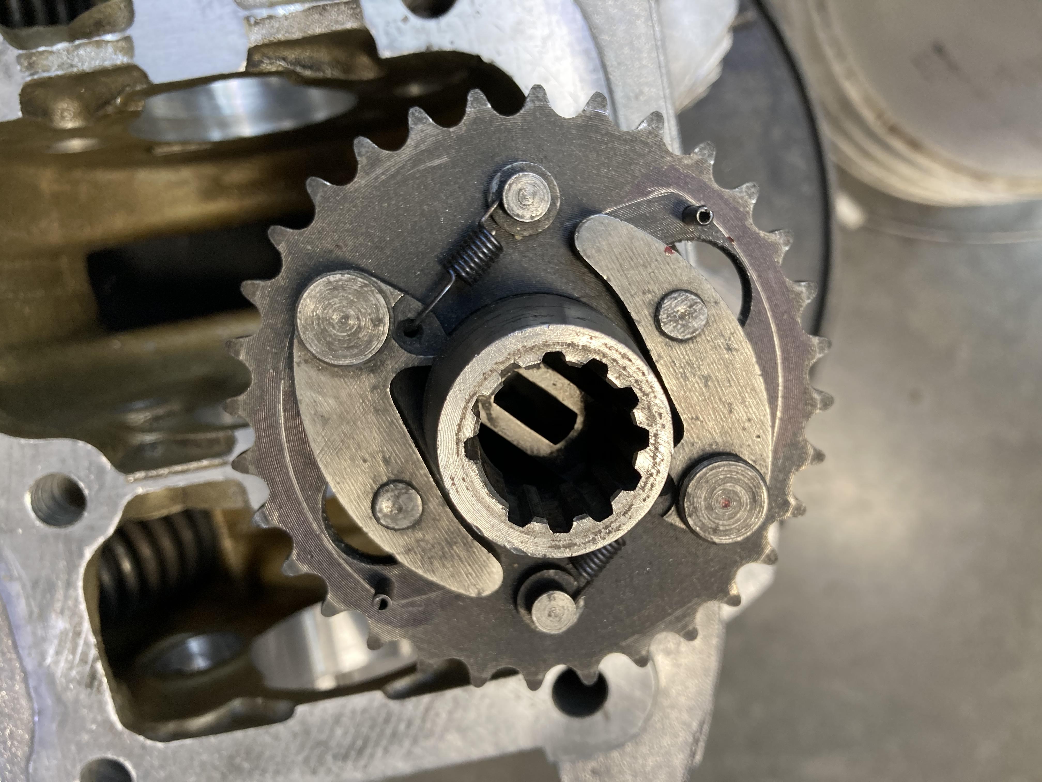
That sounds odd. My paper gasket is .17mm. When I laid a straight edge across the gears and inner housing face I was barely able to get a .08mm feeler between both faces. Bill Silver specs .04-.08mm, max .1mm clearance (pg 26-27). I even put one together, tightened down, with no gasket and no oil and was able to spin the drive wheel. My question would be where did you place the two washers?. They should both be on the outsides of the housings on the drive wheel shaft; one between wheel and housing, the other between housing and circlip. IOW's, no washers next to the gears inside the housing halves.
At the very bottom of page 26 and the top of 27 are Bills three specs. The FSM has 3 specs too but lists packing thickness at .4mm, which I assume to be gear side clearance plus gasket. Mine is .08 +. 17 =.25 , a lot less than .4, for sure. Seems like a lot to me and the one runs fine with no gasket ( just side clearance). I don't know why your's would bind when torqued down, they all have some side clearance like .04- .09 as Bill said.
I realized we are looking at a different bike in the download, as I have the CL77 version that I purchased. While it has a picture of the oil pump which is from the FSM I believe there are no specs on my download. When you get yours reassembled I am curious how easily the large gear spins. Mine did spin easily with a little resistance after I did the Permatex treatment vs a lot of resistance with only the gasket. The large gear will not freewheel and really spin easily though with continued momentum.
Bill does talk about not having too much space or clearance, as it will affect the oil pump with pressure loss around the spinning gears?


Any words of wisdom or tricks to installing 3 piece oil rings?
,install the little center divider piece first,then install each small,thin ring one after the other.Hi Tom
I install the expander and then each ring placing them @45 degrees away from the expander joint, one on either side so there's a 90 degree separation.Any words of wisdom or tricks to installing 3 piece oil rings?
I install the expander and then each ring placing them @45 degrees away from the expander joint, one on either side so there's a 90 degree separation.
Either works well.Thanks. So like 10:30, 12:00, 1:30. Or 7:30, 12:00, 4:30?
