A C78 project

Only got a few hours in this week but managed to clean up a few pieces. The rear shocks cleaned up nicely but I found that one of the shocks has a plastic cover and the other one a metal cover. I tried to disassemble the shocks to get the covers off but couldn't get the top mount to separate from the cover. I made jig for the top mount to protrude through while I compressed the top of the cover but all it did was compress the entire shock - it wouldn't let go.
20260116_220507.jpg
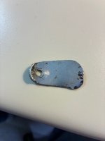
I next went after the side covers which were chromed by the PO. The left side cleaned up ok but the right cover has some serious rust perforations. I haven't yet decided if I will keep the chrome. I could rebuild the right cover with some fiber glass and then paint the lower 1/3 of the cover and do the same on the left cover so they match. The other alternative is to sand the chrome and repaint both covers, or buy a new right cover and paint both.
20260116_220834.jpg20260116_220905.jpg
The strange thing about the chrome job is that it looks like they chromed the piece without removing the paint from the inside of the covers. The red color in under the chrome!
20260116_221033.jpg

I have had the crank soaking for about a month now and every few days I would force the cleaning fluid into the crank bearings and con rods using a syringe. The end needle bearing I took off and cleaned thoroughly. I gave it all a good going over with compressed air and then oiled everything up while it waits to be re-installed. All bearings and con rods turn smoothly with no rough spots. It's the best I can do without taking it apart - for which I don't think I would tackle anyway and I doubt there is anyone in my area that could do it either.

20260116_173321.jpg
 
Hi Boddy,
Yeah, I'm about to split the cases on my '66 305, hope I can get away with a good clean up and that all the crank bearings feel ok. I'm definitely not able to to pull the crank apart if something feels wonky. Thanks for posting!
Art
 
I ordered a set of cables from one of those Thai suppliers that had a good rating. The cables arrived in about 2 weeks by post. The quality looks pretty good except for the barrel end of the clutch and brake cables.

The barrel is quite a bit smaller than what it should be and they wrapped a piece of plastic around the barrel to beef it up a bit.

Question for those that might have bought the same cables - have there been any issues with the lever flopping around since there is space between the barrel and the hole in the lever? Should I build a little mould and attempt to beef it up with some solder or will the heat make the wires brittle?

20260128_141832.jpg20260128_141806.jpg
 
Go to home depot. Get yourself a piece of tubing in the metals aisle that fits the hole in the lever. Drill out a piece to fit the barrel. Cut a slot in it for the cable.
 
I like that idea, no worries about heating the wire.
But remember to lube the outside of the add-on sleeve just as you would the barrel itself, and maybe even a drop or two on the barrel in case it moves inside the sleeve, just so the barrel won't flex the end of the cable and cause it to weaken.
 
I ordered a set of cables from one of those Thai suppliers that had a good rating. The cables arrived in about 2 weeks by post. The quality looks pretty good except for the barrel end of the clutch and brake cables.

The barrel is quite a bit smaller than what it should be and they wrapped a piece of plastic around the barrel to beef it up a bit.

Question for those that might have bought the same cables - have there been any issues with the lever flopping around since there is space between the barrel and the hole in the lever? Should I build a little mould and attempt to beef it up with some solder or will the heat make the wires brittle?

View attachment 54600View attachment 54601
I bought a set of those Thai cables for the 160 - had issues with fit on all but the throttle cable.
 
I ordered a set of cables from one of those Thai suppliers that had a good rating. The cables arrived in about 2 weeks by post. The quality looks pretty good except for the barrel end of the clutch and brake cables.

The barrel is quite a bit smaller than what it should be and they wrapped a piece of plastic around the barrel to beef it up a bit.

Question for those that might have bought the same cables - have there been any issues with the lever flopping around since there is space between the barrel and the hole in the lever? Should I build a little mould and attempt to beef it up with some solder or will the heat make the wires brittle?

View attachment 54600View attachment 54601
Hey Boddy,
Thanks for the heads up on the cables, I bought a set but neglected to closely scrutinize them yet.
 
Did a little more cleaning of parts today and made arrangements to take the engine parts to a vapor blaster this weekend who is about 1.5 hours away.

I also got some parts in from CMSNL after a long detour from the Netherlands to Oakland, Memphis, New York, Montreal then to me. Mostly a bunch of o-rings, circlips, cam chain and a dip stick. One thing I was very pleased about finding were the special "blind bolts" and cap nuts for the handle bars. They looked good in the pictures but 'they just don't make 'em like they used to'.

The old hardware is on the left the new on the right. So puny...
20260203_114921.jpg20260203_115751.jpg
 
When you completely disassemble a bike you end up with many boxes of part. I have been going through them and slowly cleaning things up. Many parts and hardware are no longer available so I would like to salvage as much as I can. The chrome fork bolts buffed up very nicely except for one as there was too much pitting. I may have to start a list of things to be chromed (once I find a place that will do it). The other choice is nickel plating which I think my zinc plater does as well.
20260207_101926.jpg
I am pleased with the bottom fork covers despite a couple of dings.
20260207_102957.jpg

I wire brushed the side stand and seeing how beefy it is, it doesn't feel very heavy. I wonder if it's some sort of alloy. There is a curve to the stand but normally if it was stressed sitting on the stand it should bend in the opposite direction. I leery about heating it up to try to straighten without knowing what it's made of. Using a magnet, it is a ferrous metal. Maybe that is the normal shape.
20260207_110216.jpg
 
I thought a better place for this would be in my build thread rather than in the parts wanted. This is the front fork lock cover.

I traced the fork lock holder on the frame on a piece of cardboard to have the outline of the lock cover. I found a piece of aluminum siding I had lying around and cut out a small piece. I traced the shape on the aluminum and did a rough cut with some tin snips.
20260213_142921.jpg 20260213_143030.jpg
I used the bench grinder to shape the piece and then smoothed the edge with a file. Used some scotch brite to clean up the aluminum. I put the piece over the lock and with a small hammer I formed the tab to the contour of the top of the lock.
20260213_143506.jpg20260213_144837.jpg

Just need to find a small shouldered screw and spring to complete the job.
 
Last edited:
I thought a better place for this would be in my build thread rather than in the parts wanted. This is the front fork lock cover.

I traced the fork lock holder on the frame on a piece of cardboard to have the outline of the lock cover. I found a piece of aluminum siding I had lying around and cut out a small piece. I traced the shape on the aluminum and did a rough cut with some tin snips.
View attachment 55066 View attachment 55067
I used the bench grinder to shape the piece and then smoothed the edge with a file. Used some scotch brite to clean up the aluminum. I put the piece over the lock and with a small hammer I formed the tab to the contour of the top of the lock.
View attachment 55068View attachment 55069

Just need to find a small shouldered screw and spring to complete the job.
Nice. The original spring was a conical (almost pyramid shaped) so it wouldn't coil bind when squished down to one wire thickness. A warpy saddle shaped spring washer could work maybe.
 
Took a look at the ignition coil today. As expected in a 60 year old component, the HT wires were stiff and cracked in a few places. I started by testing the coil to see if it was salvageable. I tested the green wire to ground and also the black to ground and there was no continuity. Next I checked the resistance between the green and black and got a reading of 3.8 ohms - not the best. I did the spark test but got nothing. I thought maybe the HT wires were at fault, so decided to remove them.

I picked off the epoxy to expose the bamboo peg that keeps the wire locked in place.
20260222_152340.jpg

Next I drilled the peg out and with a twist of the wire I was able to pull it out cleanly.
20260222_153235.jpg

I did the same for the other HT wire, then unsoldered the leads from the contacts
20260222_154734.jpg

I drilled out the rivets to get the coil off the mounting bracket.
20260222_161639.jpg

I soldered new wires to the contacts and redid my tests. Got zero continuity when testing each wire to the metal post (ground) and still got 3.8 ohms between black and green wires. Tried the spark test again with some temporary HT leads stick into the coils but still no spark.

I guess it's time to invest in a new coil and leads. I see some have gotten the 4into1, 5ohm double lead coil. I also saw that this coil requires some mods to the mounting bracket.

Any other suggestions for a coil and HT wire?

I plan to keep the original caps and get the covers zinc plated.
20260208_161154.jpg
 
This is the front fork lock cover.
Sorry to be late as I was just reading thru your thread. I think this is the lock cover you were referring to. It has been floating around in my shop(s) for years.
It's your if you want it. It weighs 4 grams so maybe not a big cost to ship it.
 

Attachments

  • IMG_7639 lock cover.jpg
    IMG_7639 lock cover.jpg
    1.3 MB · Views: 4
  • IMG_7640 lock cover.jpg
    IMG_7640 lock cover.jpg
    1.2 MB · Views: 4
Sorry to be late as I was just reading thru your thread. I think this is the lock cover you were referring to. It has been floating around in my shop(s) for years.
It's your if you want it. It weighs 4 grams so maybe not a big cost to ship it.
Very generous of you Spokes. It looks a lot sturdier than my home made one.
I will PM you.
 
The handle bars I purchased needed some tweaking for the throttle cable holder. There were no slots for the little ears. Got out the Dremel and a carbide bit and made the slots. Did a dry fit of everything and the throttle has a tight spot. The hinge slides freely in the HB slot and the pipe turn freely in the switch. When assembled it doesn't work so great. I suspect it's the hinge piece itself as there is some wear in the diagonal cutout.

In order to pass the safety check the throttle needs to snap back and this one won't do that at the moment.

Any tricks for getting a smooth operating throttle. Should I file the edge of the diagonal cutout to make it smooth or just buy a new hinge piece?

20260305_143500.jpg
 
Any tricks for getting a smooth operating throttle.
Yes.
1.) Round all sharp edges and polish rounded edges.
2.) Smooth out and polish top surface of the slide.
3.) Remove burrs (see step 1)
4.) Clean the inside of the handlebar slide and try to smooth the bore out with 400 grit or finer sandpaper. a 12GA shotgun barrel brush chucked in a drill does a nice job.
5.) lightly lubricate slide bore with 3 in 1 oil or any light gun oil. Dry graphite lube is best.
6.) Clean throttle cable and lubricate lightly. Too much lube for this type of throttle makes it sticky. (My experience)

Good Luck!
 
Also received my bearings for the cam shaft and wheel hubs. I though it was a Canadian supplier but it looks like they actually came from the UK and are manufactured in Italy. They were ordered Dec 4th and arrived today.
View attachment 53360
Hi Boddy,
Are your replacement wheel bearings sealed? I just pulled the sprocket hub on my 305 Dream project and see the bearing is unsealed. I suspect the bearing is in excess of 55 years old and while it feels ok, I'm thinking of replacing it and with a sealed one (6205-2rs c3). Thoughts? I also suspect the wheel bearings are unsealed too (and old), I'd prefer to go with sealed ones for the same reason of low/no maintenance.
Thanks,
Art
 
Art, I went with the original unsealed wheel bearings. When I took mine apart there was plenty of grease in there and the bearings were smooth turning. I decided to replace them anyway. There are oil seals on the outside to keep any moisture out so I did not see the need to go with sealed bearings.
 
Yes.
1.) Round all sharp edges and polish rounded edges.
2.) Smooth out and polish top surface of the slide.
3.) Remove burrs (see step 1)
4.) Clean the inside of the handlebar slide and try to smooth the bore out with 400 grit or finer sandpaper. a 12GA shotgun barrel brush chucked in a drill does a nice job.
5.) lightly lubricate slide bore with 3 in 1 oil or any light gun oil. Dry graphite lube is best.
6.) Clean throttle cable and lubricate lightly. Too much lube for this type of throttle makes it sticky. (My experience)

Good Luck!
Yes, and when it isn’t working smoothly after that, you could install a stiffer spring in the carburettor for the time being.
 
On my bike the diagonal slot edges on the hinge were rounded slightly and the throttle tube would bind up occasionally and create a tight spot. I suspect from the throttle tube riding up on the rounded edge. I replaced with a new hinge and works perfectly now.
 
On my bike the diagonal slot edges on the hinge were rounded slightly and the throttle tube would bind up occasionally and create a tight spot. I suspect from the throttle tube riding up on the rounded edge. I replaced with a new hinge and works perfectly now.
I think I will be replacing that hinge piece as there is wear in the slot area.
 
Mounting the Magna coils is a pain but at least you can fit the extra long wires that many other coils don't come with. My Dream runs better with these 5ohm mamas anyway.
 
Art, I went with the original unsealed wheel bearings. When I took mine apart there was plenty of grease in there and the bearings were smooth turning. I decided to replace them anyway. There are oil seals on the outside to keep any moisture out so I did not see the need to go with sealed bearings.
Thanks Boddy! I found the same here, plenty of grease & smooth action.
 
Yes.
1.) Round all sharp edges and polish rounded edges.
2.) Smooth out and polish top surface of the slide.
3.) Remove burrs (see step 1)
4.) Clean the inside of the handlebar slide and try to smooth the bore out with 400 grit or finer sandpaper. a 12GA shotgun barrel brush chucked in a drill does a nice job.
5.) lightly lubricate slide bore with 3 in 1 oil or any light gun oil. Dry graphite lube is best.
6.) Clean throttle cable and lubricate lightly. Too much lube for this type of throttle makes it sticky. (My experience)

Good Luck!
I ended up filing the diagonal groove in the hinge to remove the wear then polished the hinge. I next followed all the steps above and now it snaps back nicely. I think it was a combination of the wear and lack of any lubricant on the throttle assembly and cable.
20260308_162448.jpg


Another question for the Dream experts. I had the base of the oil pump vapor blasted and despite my best efforts to seal it up, some grit got in there. I took it apart and cleaned everything but when I put it back together there was some binding. Previously there was no binding with the new gasket. Should I use a bit of gasket cement to make the gasket a bit thicker as was suggested in a previous post, or should I cut a new gasket out of thicker material, or try to find a new oil pump gasket.
 
I'm not a fan of gasket maker for thickness' sake, but that's just me. Cut a new thicker gasket. If the thicker gasket relives binding, then your good to go. Or cut a thin second gasket and add two gaskets. One just has to make sure drive gears mate and not be pushed into each other. Just my 2 cents worth.
 
I think when I re-used the original gasket it had been crushed somewhat and now there is less clearance between the case and the gears. I will cut a new gasket and give it a shot.
 
A gasket always crushes when you torque the fasteners, that's why I measure the axial play on the cams on the CB450's three times. The first time to find out what is needed, then I use a gasket with 20% extra thickness, and after torquing the bolts I measure if the gasket material is indeed crushed 20%. Depending on the gasket material, and the initial thickness and the torque on the fasteners, I try to predict this percentage.

Coming back to your question, the best way is to measure the gap you need with a feeler, calculate the gasket thickness, and decide what you want to do. I think that the blasting material is not responsible for the binding, especially when you used vapor blasting. I think something else is responsible for binding. If you mirror the gear does it bind also ?

In my experience, used gears are seldom perfectly flat, wear patterns are specific for a side. The soft aluminum of the housing will wear, and that's one-side, thus normal, but the shaft bearing is a hardened steel insert, and will wear into each other, the wear pattern on the gear is therefore an "imprint" of the surface against which it rotates. If you mount it the other way, it could bind due to the area's are not "fitting" into each other anymore.
 
the wear pattern on the gear is therefore an "imprint" of the surface against which it rotates. If you mount it the other way, it could bind due to the area's are not "fitting" into each other anymore.
Excellent point!
 
In my experience, used gears are seldom perfectly flat, wear patterns are specific for a side. The soft aluminum of the housing will wear, and that's one-side, thus normal, but the shaft bearing is a hardened steel insert, and will wear into each other, the wear pattern on the gear is therefore an "imprint" of the surface against which it rotates. If you mount it the other way, it could bind due to the area's are not "fitting" into each other anymore.
That makes perfect sense. I took close up pictures of the gears before I took it apart initially and the gear without the pin has a couple of pit marks facing up. I will make sure that gear is oriented the right way. The other gear with the pin will be 50-50 if it's in it's original position.
 
I got some pieces back from vapor blasting and the head and cylinder seem to have a really rough casting. Maybe all the oil and grease was camouflaging all this but after cleaning it seems really rough. Could it be corrosion that was blasted away leaving this pock marked surface? Anybody come across this before?
20260310_185259.jpg


20260310_185306.jpg
 
It depends on the year of manufacturing, some cilinders are like this, but in your case I think it's a combination of oxidation that is blown away and a sandcastle that went moderate. I bought a NOS CB450 K0 cylinder a week ago (50 euro's, can you believe it ?), it was a very early one, and the surface is like yours. Sandcasting is in many cases responsible for this kind of roughness, just like my K0 cylinder. Remember that the CB750'69 model was sandcasted as weel, hence the name sandcastle, and those engine parts sometimes the same roughness.

Maybe optical it isn't the nicest head, but from a functional point of view this is an ideal situation when it comes down to cooling.
 
There is a real difference in smoothness between the top cover and the head. I might give up a bit of cooling for a little more smooth look so the pieces blend together. I will see if I can knock down at least the high points.
 
There is a real difference in smoothness between the top cover and the head. I might give up a bit of cooling for a little more smooth look so the pieces blend together. I will see if I can knock down at least the high points.
The top cover is a different part, and molded with a different method, and probably at an other facility, so the top cover surface differs from the cylinder head.
 
The top cover is a different part, and molded with a different method, and probably at an other facility, so the top cover surface differs from the cylinder head.
The top cover is actually pretty smooth, more like the upper and lower cases, so quite a contrast to the head and cylinder.
 
Thought I would post some pics of some of the parts I got back from vapor blasting last weekend. Some came out better than others. My lower case was covered in grease and protected from corrosion. Here is when I took it apart, after cleaning and then after vapor blasting.
20251116_132702.jpg 20251117_171955.jpg 20260318_205858.jpg
Some other parts...
20260318_205643.jpg 20260318_205718.jpg 20260318_211202.jpg

The upper case didn't come out as well due to all the corrosion from mouse nest and pee that was in the air filter area. There were big pock marks in the aluminum so I'm going to have to fill the holes and paint the upper an lower cases so they match. Corrosion was especially bad around the oil filler hole. I've been using a product called Steel-Tech which is a 2 part putty that you mix together. It hardens in about 20 minutes and cures in an hour. It's hard as steel but it can be sanded. Label says it can stand temps up to 500F.
20260316_142307.jpg 20260318_205405.jpg 20260318_205412.jpg

It's time consuming but the end result will be worth the smoother finish. I usually have to fill the area, sand, apply another coat and sand again. A before and after shot of the rear part of the upper case.
20260316_142311.jpg 20260318_205342.jpg
 
Nice work, Brad. I think that's a great use for the Tech Steel. I was happy to learn about that product from @Flyin900, although I've been using the presumed equivalent JB Steel Stik south of the border.
 
Also got some parts in today. Managed to find some genuine Honda footpeg rubbers from Partzilla. Got the 5ohm coil from 4into1 and the start of a tool kit also from Partzilla.
20260318_210757.jpg

The tools pictured were about $25 which is quite a bit less that what they are asking on flea-bay. Just need to find a tool pouch and get a couple of pieces I had zinc plated. I know I had a bunch of Honda spark plug wrenches, just need to locate them.
20260318_210233.jpg
 
Nice work, Brad. I think that's a great use for the Tech Steel. I was happy to learn about that product from @Flyin900, although I've been using the presumed equivalent JB Steel Stik south of the border.
Thanks. Yeah it was @Flyin900 that put me onto this when I was doing my CB450.

I also found that I can use an Exacto knife with the chisel blade to knock down the lumps and shave off layers to get it almost flat with the surface, Then is just a bit of sanding to even out the edges.
 
Getting a little time here and there to putter on the Dream and decided to look at the front wheel today. The tire looks original - it's a Nitto 3.25x16. Will have to find some replacements. Was checking out the Coker narrow whitewalls but at $230 each plus I need to factor in exchange and shipping, it's getting out of my comfort zone.
20260323_160655.jpg
I cleaned up the brake dust in the hub somewhat and found a dynastic date both in the hub and on the brake shoes - tells me these shoes were never replaced.
20260323_155951.jpg 20260323_155938.jpg
There is a dent in the rim, probably front hitting a curb as the front fender is also slightly smooshed in the usual place. I think the same impact also took a chunk out of the rim of the hub. I am debating on whether to try and find a new hub or leave as is.
20260325_144803.jpg 20260325_151751.jpg

As you can see, I unlaced the wheel as I will throw the spokes into the pile of stuff to be zinc plated. The nipples appear to be brass with no chrome or zinc on top, so i will just clean and clear coat them.
With all the spokes out of the way I cleaned up the rim which had mostly surface rust and a few pit marks.
20260325_145637.jpg 20260325_153616.jpg

The bead area had the typical rust due to moisture but got most of it out. I will treat the rust and then paint or clear coat the interior to keep the rust at bay. There are even traces of the original paint Honda used around the spoke area. Tomorrow I will cut a block of hardwood to the contour of the rim and use that to bang out the dent which luckily is only on one side.
20260325_164657.jpg 20260325_164722.jpg
 
If you’re painting the hub I wonder if something like tech steel could be shaped to repair that cracked lip?

Replacements do seem to be out there on eBay - kind of a wide mix of condition.
 
If you’re painting the hub I wonder if something like tech steel could be shaped to repair that cracked lip?

Replacements do seem to be out there on eBay - kind of a wide mix of condition.
I see there are a few hubs out there for reasonable prices. I might try to repair with tech steel and see the result before I buy a new hub.
 
Tried repairing the front hub with some Tech Steel. Got a piece of shim stock to fit on the inside of the lip to keep the inside contour as even as possible. I thought about drilling some vertical holes to put some wire or pins in place to strengthen the patch but there is just not enough width for any reinforcement. I mixed up some tech steel and applied it.
20260329_165047.jpg 20260329_165027.jpg
I let the product cure and then began to file down the excess. As I got down to the thickness of the lip there was just not enough material to keep the patch stable and it broke free. A replacement hub is in my future.

Continuing with the front wheel, I wire brushed and sanded the spokes is preparation for zinc plating the spokes. The nipples oddly enough look like brass and they polished up nicely.
20260329_150557.jpg 20260329_153501.jpg

I bought the 4into1 coil but it's not a direct fit to the coil bracket. Not having any welding equipment, I decided to fabricate some L brackets out of some aluminum stock. I bent the aluminum into an L shape then cut two pieces out and filed them to size. I decided to use 2 counter sunk screws to attach the L bracket to the stock coil holder so that the coil wouldn't stick out any more than necessary. The rivets that held on the original coil were quite large so I cut down a couple of washers to fit the bracket and narrow the opening.
20260330_171915.jpg 20260330_171930.jpg

I mounted the coil with some 6mm screws, nuts and lock washers. I will take it all apart now so I can put the bracket and my cut down washers in the zinc plating pile.

20260330_172334.jpg
 
Back
Top Bottom