
Yeah, none of them had grommets in the exit for the wiring, but the stock bars were chamfered. Still sharp enough to cut stubborn, stiff old sheathing though.From what I can see, they don’t use a grommet in the center exit? I take it the hole is just chamfered to avoid abrasion then. May add one just because.
-
Don't overlook our Welcome Package, it contains many links to important and helpful information about functions at VHT like posting pictures and sending PMs (private messages), as well as finding the parts you need.
AD
You are using an out of date browser. It may not display this or other websites correctly.
You should upgrade or use an alternative browser.
You should upgrade or use an alternative browser.
Twin 160's - since you can never have too many projects
- Thread starter EzPete
- Start date
ballbearian
Veteran Member
The inside edge sharp burrs can be smoothed with a dremel and fine diamond grinder tip.Yeah, none of them had grommets in the exit for the wiring, but the stock bars were chamfered. Still sharp enough to cut stubborn, stiff old sheathing though.
I'm Mr. Crude, I just used a round file. Or as my father called it, rat tail file.The inside edge sharp burrs can be smoothed with a dremel and fine diamond grinder tip.
ballbearian
Veteran Member
Dad knew his stuff.I'm Mr. Crude, I just used a round file. Or as my father called it, rat tail file.
And what he didn't know, he made up on the fly.Dad knew his stuff.
Build the plane in the air.And what he didn't know, he made up on the fly.
He was pretty damn good, but not that good!Build the plane in the air.
Slow moving… real life getting in the way a lot here.
Anyway… got back to town this morning and cleared the calendar for a bit. Pulled the crank out of the kerosene and pushed a good amount of WD40 through what parts of the okay passages I could get to - I think I approximated the method @Flyin900 did on his, sealing the bearing up a bit (I wedged a doubled up inner tube piece up against that race) there’s a definite point of entry and exit in there and it seemed like WD was coming up around the lower connecting rod - calling it a win, despite the tiny bit of rust staining.

And then some shiny stuff showed up.
 But that’s for later. Engine cases replaced the crank in the kerosene to see if some of the gunk can get softened up a bit. Can’t take it to the machine shop in this condition.
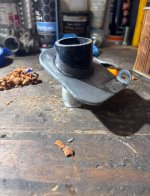
While petrochemicals do their thing I moved on to the air cleaner reconstruction. I’ve got the covers so we can go function > form to an extent here.

Starting with a shell

Scraped down to the old epoxy and separated the front as I need to solve the missing “boot”.

1 3/8 PVC is about 2mm wider than it’s supposed to be so I “turned down” a section with some sandpaper, marked it up to get square in the tube

Epoxied that lip in, as this will give something for the 32mm silicone tube from a turbo kit (reinforced).

Horsed around getting the angle and height right.
Little epoxy on the tube>lip inside, and a base of black RTV to seal

Foam wrap with some E6000 in the channels, some globs of JB weld on the mesh frame to cap connection, and a piece of packing tape to hold it all together while it all cures.
Foam was a bit thick. The eyeball tape measure failed.

Function over form though. It’ll be hidden behind the covers anyway. I may run a single long skinny bolt from cap to cap just to tie it all together when it’s bolted on the bike.
Anyway… got back to town this morning and cleared the calendar for a bit. Pulled the crank out of the kerosene and pushed a good amount of WD40 through what parts of the okay passages I could get to - I think I approximated the method @Flyin900 did on his, sealing the bearing up a bit (I wedged a doubled up inner tube piece up against that race) there’s a definite point of entry and exit in there and it seemed like WD was coming up around the lower connecting rod - calling it a win, despite the tiny bit of rust staining.
And then some shiny stuff showed up.
But that’s for later. Engine cases replaced the crank in the kerosene to see if some of the gunk can get softened up a bit. Can’t take it to the machine shop in this condition.While petrochemicals do their thing I moved on to the air cleaner reconstruction. I’ve got the covers so we can go function > form to an extent here.
Starting with a shell
Scraped down to the old epoxy and separated the front as I need to solve the missing “boot”.
1 3/8 PVC is about 2mm wider than it’s supposed to be so I “turned down” a section with some sandpaper, marked it up to get square in the tube
Epoxied that lip in, as this will give something for the 32mm silicone tube from a turbo kit (reinforced).
Horsed around getting the angle and height right.
Little epoxy on the tube>lip inside, and a base of black RTV to seal
Foam wrap with some E6000 in the channels, some globs of JB weld on the mesh frame to cap connection, and a piece of packing tape to hold it all together while it all cures.
Foam was a bit thick. The eyeball tape measure failed.
Function over form though. It’ll be hidden behind the covers anyway. I may run a single long skinny bolt from cap to cap just to tie it all together when it’s bolted on the bike.
Attachments
Looking good there Pete.
I did PM message Graham Curtis in England about the CL160 crankshaft and the internal sludge traps. He sent me a bunch of pictures and info on the CL160 crank. There are extensive sludge traps in there just like the other CB450 DOHC and CL77 cranks. As suspected you cannot clean the cranks without pressing them apart for a proper cleaning. It is beyond my skill level and you need at least a 5 ton press and some metal blocks to set up for the operation.
I feel I have got something fluid wise going through the journals to the conn rod big ends and hopefully it will suffice.
Yep. That’s way out of my scope as well. I’ll stick to getting good oil, getting it good and hot and changing it regularly. If it blows, it blows.Looking good there Pete.
I did PM message Graham Curtis in England about the CL160 crankshaft and the internal sludge traps. He sent me a bunch of pictures and info on the CL160 crank. There are extensive sludge traps in there just like the other CB450 DOHC and CL77 cranks. As suspected you cannot clean the cranks without pressing them apart for a proper cleaning. It is beyond my skill level and you need at least a 5 ton press and some metal blocks to set up for the operation.
I feel I have got something fluid wise going through the journals to the conn rod big ends and hopefully it will suffice.
ballbearian
Veteran Member
Nice work. The original AF boots on mine are sure to die some day.
ballbearian
Veteran Member
I would love to see Graham's pictures of 160 crank breakdown. All of them really.Looking good there Pete.
I did PM message Graham Curtis in England about the CL160 crankshaft and the internal sludge traps. He sent me a bunch of pictures and info on the CL160 crank. There are extensive sludge traps in there just like the other CB450 DOHC and CL77 cranks. As suspected you cannot clean the cranks without pressing them apart for a proper cleaning. It is beyond my skill level and you need at least a 5 ton press and some metal blocks to set up for the operation.
I feel I have got something fluid wise going through the journals to the conn rod big ends and hopefully it will suffice.
Need to archive this stuff, perhaps in a separate thread and a sticky too.
I did ask Graham permission to use them and waiting for his response. Then AD will need to help me with the migration of the info from the PM.I would love to see Graham's pictures of 160 crank breakdown. All of them really.
Need to archive this stuff, perhaps in a separate thread and a sticky too.
ballbearian
Veteran Member
It would be great to add them to our killer Crank Cleaning sticky thread under Tips and Tricks.I did ask Graham permission to use them and waiting for his response. Then AD will need to help me with the migration of the info from the PM.
Here it is. Long live this thread.
Crankshaft Cleaning
I've been following all of the build threads on this site and seeing the damage that foreign debris in the oil can cause I started to get paranoid about properly cleaning the crankshaft of my 71 CB450. In Teebo's most recent thread 12ozPBR mentions cleaning the flywheel area near the main...
Without press work, another option is drilling out the con rod pin plugs to clear through to the oil gallery/sludge traps.
A suitable plug material needs discussed. Lead fishing weights, aluminum rod stock?
Could a thin hooked piano wire or guitar string be used the scrape the tight 160 sludge traps?
I have 150,160, 305 and 350 cranks to clean out and am looking forward to Graham, or anyone else who can add perspective and pics to this pursuit.
Engineer Jay told me Lee plugs, and another name I can't recall as well, are available and will work. That was during my thinking the 4 speed crankshaft was the one I would use because the inner two main bearing races won't move back enough to reach the feed orifice in the sludge trap.A suitable plug material needs discussed. Lead fishing weights, aluminum rod stock?

Plugs
Lee Plugs offer an easy-to-install, helium leak-tight seal without the use of O-rings or sealants. A wide range of options exist for sealing metal and plastic housings.
 www.theleeco.com

Those little slot cut outs to allow you to pry the cover off - that's all it takes for little critters to get in a build a home!How does that much dirt even get there?
I'm glad I'm not the only one who works in flip-flops or sandals now and then LOL“Remove oil filter cover”
Sure, pal, sounds easy that way.
How does that much dirt even get there?
Your in frostbite territory now up here!I'm glad I'm not the only one who works in flip-flops or sandals now and then LOL
Yeah, that's only 9 months a year footwear here. But fortunately no frostbite in the other 3 months.Your in frostbite territory now up here!
mike in idaho
Veteran Member
How is removing/replacing the crankshaft plugs going to affect the balance factor of the crank assembly?It would be great to add them to our killer Crank Cleaning sticky thread under Tips and Tricks.
Here it is. Long live this thread.
Crankshaft Cleaning
I've been following all of the build threads on this site and seeing the damage that foreign debris in the oil can cause I started to get paranoid about properly cleaning the crankshaft of my 71 CB450. In Teebo's most recent thread 12ozPBR mentions cleaning the flywheel area near the main...www.vintagehondatwins.com
Without press work, another option is drilling out the con rod pin plugs to clear through to the oil gallery/sludge traps.
A suitable plug material needs discussed. Lead fishing weights, aluminum rod stock?
Could a thin hooked piano wire or guitar string be used the scrape the tight 160 sludge traps?
I have 150,160, 305 and 350 cranks to clean out and am looking forward to Graham, or anyone else who can add perspective and pics to this pursuit.
Makes it easier to not track everything from the garage into the house.I'm glad I'm not the only one who works in flip-flops or sandals now and then LOL
While they are likely lead or something similar that's kinda heavy for their size, they're not very large. I think the ones visible on the 4 speed 450 crank are about 6mm or soHow is removing/replacing the crankshaft plugs going to affect the balance factor of the crank assembly?
I did slide over the outer bearing on the rotor side of the CL160 crank after removing the large C Clip. I could see the pin used into the side of the crank weight. I suspect it was a passageway into the main conn rod journal oil feed. It looked to be about 4mm diameter as a best guess and a round metal of some type. It wasn't really soft when probed. So it would require a drill bit to drill out and remove properly.While they are likely lead or something similar that's kinda heavy for their size, they're not very large. I think the ones visible on the 4 speed 450 crank are about 6mm or so
My concern would be the metal chips moving inward as it is drilled out. I am sure you could remove them if done carefully. I don't think once replaced the difference in weight of one metal plug vs another given the small size would be enough to cause an imbalance on the crankshaft.
You would need to remove the large pressed on bearing on the oil spinner crank side to access the other metal pin. Doing that without damaging that bearing would be a question for Graham. On the CL77 I considered replacing that bearing since it was very slightly notchy. The only NOS one I could find was $200 US plus shipping. It is a special bearing with the hole for the retaining pin in its outer case to locate it vs a generic aftermarket one I found. It was a pass on redoing a replacement bearing for that motor.
ballbearian
Veteran Member
Re-reading the sticky Crank Cleaning thread last night was interesting.I did slide over the outer bearing on the rotor side of the CL160 crank after removing the large C Clip. I could see the pin used into the side of the crank weight. I suspect it was a passageway into the main conn rod journal oil feed. It looked to be about 4mm diameter as a best guess and a round metal of some type. It wasn't really soft when probed. So it would require a drill bit to drill out and remove properly.
My concern would be the metal chips moving inward as it is drilled out. I am sure you could remove them if done carefully. I don't think once replaced the difference in weight of one metal plug vs another given the small size would be enough to cause an imbalance on the crankshaft.
You would need to remove the large pressed on bearing on the oil spinner crank side to access the other metal pin. Doing that without damaging that bearing would be a question for Graham. On the CL77 I considered replacing that bearing since it was very slightly notchy. The only NOS one I could find was $200 US plus shipping. It is a special bearing with the hole for the retaining pin in its outer case to locate it vs a generic aftermarket one I found. It was a pass on redoing a replacement bearing for that motor.
G-Man said he would drill and tap M6 plugs, on the 450s, to pull them. He didn't say what he re-plugged them with but did say weight balancing of the flywheel halves was not as important as dial gauge alignment during re-assembly.
Jensen said he made his own plugs for replacement after cleaning, he didn't say with what material.
Cleaning out the conrod central oil bore gets closer to full flow to the rod bearings but to get to the rod pin cross drillings requires the outer halves be removed with a press.
Good pics in that thread, these from 12ozPBR. See 4th pic in post #119.
Crankshaft Cleaning
Even extra witness/scribe marks is good in case any get obliterated somehow. Crank sprocket positioning does seem crucial, especially since we don't have ultra expensive adjustable cam sprockets. I've heard Capellini does make one, but may be for 350's, never seen it. This is very interesting.
GaryJames
Veteran Member
As long as they are safety rated flip flops you are fine…………..I'm glad I'm not the only one who works in flip-flops or sandals now and then LOL
Kept grinding away here.
Cases all prepped and ready to take to get vapor blasted to hopefully bring back some of the aluminum finish. There’s a fair amount of corrosion under the caked on dirt I clawed off there.
Got the second air cleaner done off the spare “bad” frame for the right side. Leaves me with an extra that still has the factory boot, which I thought would look more odd than both having the same “refurbishment”.


Made sure I had all the side covers accounted for and started working through whatever superhuman clearcoat Honda got their hands on in the 60’s

As luck would have it when cleaning the brake panels, someone had done the front brakes very shortly before the last time this bike was run, which means really good used front brake shoes - no small feat as the only replacements are $80. Likely won’t get so lucky on the next one, but a win is a win.
Now to get the frame bits cleaned up and de-rusted for paint. A bunch of Internet wandering landed Ben on Honda Paint Code R81 in Milano Red as a commonly available red that appears to be a pretty good match.
Cases all prepped and ready to take to get vapor blasted to hopefully bring back some of the aluminum finish. There’s a fair amount of corrosion under the caked on dirt I clawed off there.
Got the second air cleaner done off the spare “bad” frame for the right side. Leaves me with an extra that still has the factory boot, which I thought would look more odd than both having the same “refurbishment”.
Made sure I had all the side covers accounted for and started working through whatever superhuman clearcoat Honda got their hands on in the 60’s
As luck would have it when cleaning the brake panels, someone had done the front brakes very shortly before the last time this bike was run, which means really good used front brake shoes - no small feat as the only replacements are $80. Likely won’t get so lucky on the next one, but a win is a win.
Now to get the frame bits cleaned up and de-rusted for paint. A bunch of Internet wandering landed Ben on Honda Paint Code R81 in Milano Red as a commonly available red that appears to be a pretty good match.
Richard Pitman
Veteran Member
Honda Milano Red car paint is what I've used on my 175's, seems to be a reasonable match for the original red paint. Then clear coated with a 2k lacquer. Same paint in both photos.


It was actually your post on that place that shall not be named that got me pointed in the direction of that color code.Honda Milano Red car paint is what I've used on my 175's, seems to be a reasonable match for the original red paint. Then clear coated with a 2k lacquer. Same paint in both photos.
View attachment 52015
View attachment 52016
Had a few hours today to dig in here and try to chip away at the years of buildup and rust and Oklahoma red clay.


Center stand took two full days in evaporust and a wire wheel - old school aluminum throttle tube was intact and similar treatment - kinda cool touch to have surviving.

Rebuilt both sets of RH controls and the LH side. @boddy wrote a much more detailed description, essentially the same process for mine - did have to solder on new leads from the starter button contact and luckily even had some proper starter wire from Vintage Connections to do this.
Of interesting note is that these two switches were completely different - I did a poor job of documenting the difference in the button and the fiber plate (you can kind of see the button difference in the photos.


As I discovered after dumping everything in the ultrasonic - nothing on either of these sets is interchangeable, with the exception of the not pictured little tensioner/stop spring for the throttle.
I wonder if the silver one is a rebuild kit - or just possibly some later or really decent aftermarket version. Or, could be more of the same with these 160’s where a lot of the parts seem to have a bit of variance.

Sadly. The LH high beam and horn switch got hacked apart at some point to avoid drilling bars. This one had the blue loom casing so must have been a used replacement at some point. Sliced that off and just went black since I’ll be drilling the bars out to get back to a factory look.

Knocked out the perches. May go a round with the dremel and see if I can get more polish to it.
Next up is these ugly bastards.
Plus fenders and forks, headlight bucket, peg stands. And tank. Gotta get this all done while we still have semi reliable paint weather.
Center stand took two full days in evaporust and a wire wheel - old school aluminum throttle tube was intact and similar treatment - kinda cool touch to have surviving.
Rebuilt both sets of RH controls and the LH side. @boddy wrote a much more detailed description, essentially the same process for mine - did have to solder on new leads from the starter button contact and luckily even had some proper starter wire from Vintage Connections to do this.
Of interesting note is that these two switches were completely different - I did a poor job of documenting the difference in the button and the fiber plate (you can kind of see the button difference in the photos.
As I discovered after dumping everything in the ultrasonic - nothing on either of these sets is interchangeable, with the exception of the not pictured little tensioner/stop spring for the throttle.
I wonder if the silver one is a rebuild kit - or just possibly some later or really decent aftermarket version. Or, could be more of the same with these 160’s where a lot of the parts seem to have a bit of variance.
Sadly. The LH high beam and horn switch got hacked apart at some point to avoid drilling bars. This one had the blue loom casing so must have been a used replacement at some point. Sliced that off and just went black since I’ll be drilling the bars out to get back to a factory look.
Knocked out the perches. May go a round with the dremel and see if I can get more polish to it.
Next up is these ugly bastards.
Plus fenders and forks, headlight bucket, peg stands. And tank. Gotta get this all done while we still have semi reliable paint weather.
Nice job on the switches. Seems to be a lot of variations in those switches from the '60's.
Yeah - I'm trying to figure out where to try and incorporate a kill switch in this arrangement as well.Nice job on the switches. Seems to be a lot of variations in those switches from the '60's.
If you could find a switch with the flasher mechanism you could maybe rig up the 3 position wiring as a kill switch.Yeah - I'm trying to figure out where to try and incorporate a kill switch in this arrangement as well.
Got started in in the tank - well, the side panels at least. Waiting on a new bottle of Rust 911 concentrate to get the little bit of rust soaked out before stripping the tank down. Luckily both chrome panels and the rubber knee pads were intact and relatively unscathed by time.

Pretty straightforward process to pull these apart.
Remove the emblem, then the 10mm bolt behind it.

Slide and wiggle the panel forward

Then pop the rubber out of its tabs (hit it with the heat gun in low for a second or two to loosen it up.)

Washed everything up hit the rubber panels with a good 303 soak while I hit the chrome with some mothers and elbow grease.


Work that rubber panel back on.
Panels done. Onto the tank next.

Pretty straightforward process to pull these apart.
Remove the emblem, then the 10mm bolt behind it.
Slide and wiggle the panel forward
Then pop the rubber out of its tabs (hit it with the heat gun in low for a second or two to loosen it up.)
Washed everything up hit the rubber panels with a good 303 soak while I hit the chrome with some mothers and elbow grease.
Work that rubber panel back on.
Panels done. Onto the tank next.
Yeah, I went down a quick search for period-correct controls that would have the turn signals and the first few were in the $150 range - probably just going to mount something near the ignition switch or see if I can find a RH control that has a Low/High switch that I can just use one pole from.If you could find a switch with the flasher mechanism you could maybe rig up the 3 position wiring as a kill switch.
ballbearian
Veteran Member
Petcocks and gas caps are unique on these. Both cleanable/rebuildable.
Yep. Petcock rebuild kit and gas cap gasket are in the ever-growing 4into1 cart. Cap itself is current in the evaporust bath with the side covers. Apart from a petrified gasket, it’s in decent shape.Petcocks and gas caps are unique on these. Both cleanable/rebuildable.

ballbearian
Veteran Member
Petcock packing is 16955-268-020 from DSS, if 4into1 kit is wrong. Gas cap has smaller center snout than most so hope other fits.
Pete, the air cleaners you refurbished. Could you confirm the left side filter has the small bump in the metal backplate? The intake rubber mount is also on the outer edge of the filter by that bump in the backplate.
This was curious. There’s two part numbers I keep seeing thrown around. 17631-253-000 and 010. 000 is $2, 010 is much harder to find. Probably just break down and order both the petcock kit and 010 from DSS.Petcock packing is 16955-268-020 from DSS, if 4into1 kit is wrong. Gas cap has smaller center snout than most so hope other fits.
It does indeed have that bump out on the “inside”Pete, the air cleaners you refurbished. Could you confirm the left side filter has the small bump in the metal backplate? The intake rubber mount is also on the outer edge of the filter by that bump in the backplate.
Here’s an annoying part of this.Petcock packing is 16955-268-020 from DSS, if 4into1 kit is wrong. Gas cap has smaller center snout than most so hope other fits.
DSS
Petcock gasket - $12
Cap gasket - $4
+shipping
Partzilla
Petcock gasket - $5 (same part)
Cap Gasket - NA
+shipping
Pete.It does indeed have that bump out on the “inside”
Does your bikes have the aluminum lower front forks slider assembly? I just ran into a real issue with discovering another PO fix. Both fork seals are leaking and I cannot get them out of the sliders. Have you pulled apart your forks yet if they are the aluminum variety?
I am going to discuss this issue on my post to see what others know or have experienced. My forks don't conform to the FSM parts fiche pictures or their design of the parts used.
Thanks
I was planning on digging into forks this weekend. Need to separate the sliders from tubes for paint and prep anyway.Pete.
Does your bikes have the aluminum lower front forks slider assembly? I just ran into a real issue with discovering another PO fix. Both fork seals are leaking and I cannot get them out of the sliders. Have you pulled apart your forks yet if they are the aluminum variety?
I am going to discuss this issue on my post to see what others know or have experienced. My forks don't conform to the FSM parts fiche pictures or their design of the parts used.
Thanks
So do you have the aluminum lowers with the same parts I noted in my post. The forks I have use a standard internal large C clip, rather than the simpler wire clip shown on the parts fiche. Mine also use an Allan bolt to secure the internals in the bottom of the slider. This Allan bolt isn't shown on the Honda parts fiche. I suspect the fiche is for the older style steel sliders???I was planning on digging into forks this weekend. Need to separate the sliders from tubes for paint and prep anyway.
I honestly haven’t even dug that far into the forks. I just yanked them out of the triple, drained the oil and put them in the “to be dealt with” tote. From outward appearance, they seem to match yours but I’ll have to see when I take them apart.So do you have the aluminum lowers with the same parts I noted in my post. The forks I have use a standard internal large C clip, rather than the simpler wire clip shown on the parts fiche. Mine also use an Allan bolt to secure the internals in the bottom of the slider. This Allan bolt isn't shown on the Honda parts fiche. I suspect the fiche is for the older style steel sliders???
So I did get one apart and Mike in Idaho indicated you don't need to remove the bottom Allan bolt, just the seal clip or C Clip. Hopefully yours come apart easier. The one is still not co-operating after some heat around the seal area and nasty thumping.
Last edited:
I’m expecting a crap ton of Cameron goodness holding them together right now. Probably get everything soaking in some penetrant, given the likelihood these seals have been baking once for 60 years.So I did get one apart and Mike from Ohio indicated you don't need to remove the bottom Allan bolt, just the seal clip or C Clip. Hopefully yours come apart easier. The one is still not co-operating after some heat around the seal area and nasty thumping.