1972 CB450 K5 Hot Mess

Interesting side note on the seller and shipping times for the handlebars, I ordered at about 9:00 AM but they showed they shipped at 6:29 AM. For a moment I thought SERN was at it again with the Hadron Collider splitting alternate time lines but then I realized the time difference is from seller being in California 3 time zones away. While alternate time lines and dimensions would have been more fun I really appreciate the seller being on the ball with USPS accepting the shipment that afternoon.

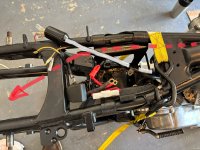
As for progress on my build after vacation and the pile of honey do's that piled up not much report, other than trying to get back on track. Cleaned up the starter motor cable and inspected after peeling off deteriorated outer protective sheath and a taped repair I found several small chaffed areas that I repaired with liquid tape and then heat shrink. I will have to find a a good substitute for the protective sheath, where it goes around and under the motor.

I also took another look at wire harness again but after removing several tape repairs where I found wires cut and twisted on repairs I cut bait and ordered the wire harness kit from Sparck Moto that includes the Regulator / Rectifier and flasher this morning. It will be super nice not to have to worry about corroded connections and shorted wires. :p
 
I cut bait and ordered the wire harness kit from Sparck Moto that includes the Regulator / Rectifier and flasher this morning. It will be super nice not to have to worry about corroded connections and shorted wires. :p
There won't be many pieces left that haven't either been replaced or fully refurbished by the time you're done.
 
Exactly and I do enjoy get a lot of satisfaction from the restoration. I also figure at my age and circumstances I may have a bit more money than time and heck I can't take it with me.
And, you know how everything in the machine is supposed to work. I really enjoy the process of trouble shooting when I can imagine how whatever is happening, could happen. You can't do that until you've spent hours getting introduced to the systems.
 
Trying to get everything together so I can get the motor in the frame but 1 step forward, 2 back. I wanted to to put the lower fork in the steering stem before I started on the engine and had inspected the steering stem races and bearings and they looked good so I said what the heck I will just reuse them. Put everything back together the other day and the steering seemed smooth as silk. Patted myself on the back and then this morning while I was laying stuff out to to visualize how I was going to do a frame over engine install I moved the the steering stem and felt a definite lock at the 12 o:clock center position and at the 10:00 to 11:00 o:clock position. Obvious that there is wear in the races. Just ordered a tapered bearing kit from 4into1 which was my initial inclination which I should have just done. Anyway back to sorting parts and seeing if I can remember where everything goes. :unsure:
 
Trying to get everything together so I can get the motor in the frame but 1 step forward, 2 back. I wanted to to put the lower fork in the steering stem before I started on the engine and had inspected the steering stem races and bearings and they looked good so I said what the heck I will just reuse them. Put everything back together the other day and the steering seemed smooth as silk. Patted myself on the back and then this morning while I was laying stuff out to to visualize how I was going to do a frame over engine install I moved the the steering stem and felt a definite lock at the 12 o:clock center position and at the 10:00 to 11:00 o:clock position. Obvious that there is wear in the races. Just ordered a tapered bearing kit from 4into1 which was my initial inclination which I should have just done. Anyway back to sorting parts and seeing if I can remember where everything goes. :unsure:
You'll never touch them again once you put tapered rollers in it, and this gives you the opportunity to lay the frame over the engine now with the weight of the front end removed.
 
Second the roller bearing races they sure make a difference in the actual tightness of the front end too. More surface area in contact with with the rollers compared to balls. And, yeah installing the frame on the engine is a heck of a lot easier than lifting that lump of dead weight into the frame, less chance for scratching of paint as well.
 
Yeah sometimes an idea that seems so obvious after the fact is so elusive, looking forward to giving it a try. I have a dim memory of the pain in the butt it was getting engine back in the CB450 I had back in the 70's. If I remember it took 2 of us and I was a lot stronger with more stamina then. :rolleyes:
 
A few updates, rolled the engine out the other day from where it sat for the last few months and wanted to double check the point gap and static timing. Followed the FSM and made sure both sets of points were set to 0.014 in middle of the 12 to 16 range. Used my Ohm meter to check the timing and the left side was perfect so went to the right side and had to adjust the points to 0.013 in. Unless I have totally goofed up I feel the timing is set but there will be nagging doubts until I hear it run. I plan on final checking the timing with a timing light.

Received the handlebars that were supposed to be from a 1973 CB450 and very pleased with them. Appeared straight and true with good chrome and didn't cost a arm, leg or both.

IMG_4927.JPG


I also got the starter cable ready for install by using Heat Shrink Braid Sleeve I ordered from Amazon as the outer sheathing. The old sheath on the cable was decomposing and also had to be removed for some minor repairs to the cable insulation using liquid tape and heat shrink. I considered just using cable as is but really wanted an extra layer of protection. The braided sleeve will provide extra protection against chaffing but is not as bulky as the original sheath. I eneded up ordering 1/2 inch sleeve as it says it will shrink to 1/2 it's size which worked well IMO, as it is tight on the cable. I will put the terminal end boots on after I get the engine in the frame and route the cable.

IMG_4926.JPG

Waiting for the right day and motivation to do the engine install. :rolleyes:
 
A few updates, rolled the engine out the other day from where it sat for the last few months and wanted to double check the point gap and static timing. Followed the FSM and made sure both sets of points were set to 0.014 in middle of the 12 to 16 range. Used my Ohm meter to check the timing and the left side was perfect so went to the right side and had to adjust the points to 0.013 in. Unless I have totally goofed up I feel the timing is set but there will be nagging doubts until I hear it run. I plan on final checking the timing with a timing light.
Sounds like you nailed it, gaps between .012" and .016" are perfect. Hopefully the advancer cooperates and you don't have to pull the plate to bend the limiter tabs in the event it over-advances, happens once in a while.
 
Installed the Rising Sun Tapered Steering Bearing Kit from 4into1 yesterday and overall no big problems despite there being no parts breakdown or instructions included. I have actually never done this upgrade before so I watched a number of videos and read the AllBalls instructions as the kit looks basically identical. One issue I did have was the large spacers that are needed to go under the lower bearing inside diameter was a bit too small to slide down on the steering stem. I used some 180 grit sand paper wrapped around a piece of 3/4 inch PVC and removed about 2 or 3 thousandths of an inch from the inside diameter to get it fit properly. The rest of the install went well with both races installed and lower seal and bearing knocked on the steering stem with no damage. :p I did get ahead of myself and forgot to grease the bearing before i installed it but I will be able to grease it on the stem with just a little extra work. I should mention I did measure the the old lower bearing set and used that measurement to determine which of the two spacer to use. The old bearing set measured 17.78 mm and the new bearing set measured 18.06 mm with the smaller spacer or about 0.011 inch difference. I test fit the steering stem to the head and every thing looks good.

Bearing kit.JPGIMG_4935.JPGIMG_4937.JPG


IMG_4939.JPG

Next step is getting the the frame wrapped around the engine.
 
Felt I had gathered sufficient mojo or cosmic energy or something and decided to get the engine in the frame today. Before that I did get the starter cable connected to the starter and wrapped under the engine using info provided here at this thread, CB450 K6 K7 Correct Starter Cable routing, thanks to everyone who contributed it was super helpful!


After doing that I laid out some cardboard and moving blankets, wooden blocks and the lower two mounting bolts. Slowly worked the engine off the blocks and dolly it was resting on and got it down on the blanket with out injury to myself or the engine. I did have the extra set of left and right engine covers on the engine just as extra protection in case it got away from me. Blocked the engine up to what I thought was level and then started working the frame over the engine. My wonderful wife wanted to help me but I finally shooed her back in the house as I had visions of her breaking a finger or something. She is willing but totally no experience with this type of stuff. Anyway after only abut 15-30 minutes I had both lower bolts in place. There are a few places that need paint touch up but nothing major. I also must have a damaged the threads a bit on one of the bolts when I had to persuade it a plastic mallet. Thankfully I ha already purchased a 12mm thread chaser so sorted that out no problem. With that I decided the gods of Honda had smiled on me as much as the were likely to so snapped a pic and started cleaning up and call it a day.

IMG_4938.JPG
 
A huge sense of accomplishment and at last a feeling I can see the beginning of the end. Still a ton to do and I am sure I am going to have a lot more questions I will need help with. Thanks in advance to everyone at VHT.
The largest and most difficult part is done now, the rest should be a lot more enjoyable.
 
Question regarding the kick starter arm install. The FSM states "The kick starter arm should;d be installed on the kick starter spindle by matching the punch mark on the spindle." I have found the punch mark on the spindle which is at the 12 o:clock position but I am not sure what I should be lining it up with on the arm. I have 2 kick start arms and I cannot find a punch mark on either of them. My knee jerk is to install it as close to vertical as I can without the pinch bole head hitting the case. As is the kick start goes nearly horizontal before engaging. Simple mechanism so I don't believe I installed anything wrong but I am quite talented in that regard. Appreciate the feedback.
 
My kick start does not have a mark either and I installed it at the 5 to 12 position. The arm engages a little before the horizontal position, so I think you are good.
 
As mentioned, there's not always a corresponding dot on the later version lever that articulates from the lower part. This position gives you maximum kicking stroke without the arm contacting the right crankcase cover.

1748956549187.png

Still amounts to about the same starting engagement position for the lever.

450 kickstart position.jpg
 
Mine is about the same. I thought it might be a tooth broken off in the internal gears, but, based on your photos and comments, maybe not. Which is good news!

Good luck with the rest of the assembly process. It's just a big relief when the boxes of parts start to disappear and cubic feet of garage space appears.
 
Wanted to give a shout out to Matt at Sparck Moto. I had ordered the Honda 450 Basic Refurb Kit which has the harness, Regulator / Rectifier and LED flasher. When I received the package I could see the side had been split open and repaired with packing tape. Upon opening I found that it was missing the Regulator / Rectifier. Reached out to Matt and he had a replacement out to me in short order. It was due to be delivered yesterday and I happened to see the mail carrier stop and put mail in our mail box and when I went to get the mail I had a number of mail items I didn't want but no package. Checked the tracking number and show it had been delivered so figured it was at a home on another road about a 1/2 mile away that has the same house number as ours. We all too often get each others mail and depending on what it is we will just take it to the other person's house. About two hours later the package was kindly delivered. As I have gotten older I try to be more understanding that there is no perfection in the mortal universe but sometimes I do have to bite my tongue and take a breath. Thanks again Matt fo getting the replacement part out to me so quickly and there is something awful nice about having a nice new harness rather than trying to deal with an old corroded and butchered original.

IMG_4941.JPG
 
Started temp piecing parts together and overall going well. No hurry and I have plenty of coffee.

IMG_4945.JPG

I do have a question about the front motor mount bolts which the parts manual show being installed right to left. The bottom one closest to the engine, washer and nut interferes with the starter cable and I am concerned there may be a chaffing problem. There is plenty of clearance if I install the bolt right to left and I can't think of any practical reason it could be reversed. Thanks for your thoughts.

IMG_4944.JPG
 
I've never worried about which direction the motor mount bolts go into the frame and brackets, mine are likely backwards now that you mention it but I don't have a starter cable either. I'd turn them all the same direction if it was mine, at least you'd have continuity.

On another note, you need to mount that chain guard while you can still lower the swingarm enough to make that short forward bolt inside the passenger peg mount accessible enough so you don't struggle with it. And remember, the starter cable goes between the starter motor and the engine.
 
Thanks, like I said I could think of no practical reason for which direction to mount the bolts. I do I have the starter cable wrapped close to the engine and behind the starter and I really appreciate the tip regarding the chain guard. :)
 
I do I have the starter cable wrapped close to the engine and behind the starter
Ah, must be an older picture prior to that then.
and I really appreciate the tip regarding the chain guard. :)
That short 6mm bolt (12mm long) is really difficult, IIRC I had to unbolt both shocks at the bottom and lower the swingarm to get that one back in after the chain guard repair.

 
I think I routed the starter cable initially like you are doing but then ran into the same problem with the bolt. I ended up routing the cable towards the outside as per the red line in the pic below.
routing2a.jpg

Ditto on installing the chain guard now before too much is i the way. There is not a lot of room to get that bolt in.
20240927_150110.jpg
 
Ah, must be an older picture prior to that then.
In the photo above I had disconnected the terminal end from the starter and pushed the cable down a bit but not all the way out so I could pull some slack while I was trying different things to get the bolt and nut installed without it rubbing on the cable. I do have the cable up against the sump but with the bolt installed left to right it appears to be OK with no chaffing risk.

Thank you again on the reminder about the chain guard. With no shocks or anything installed I was able push the rear fork down enough to install that pesky middle bolt with 1/4 drive 10 mm through the hole in the frame where the rear step/muffler mount is.

Frame area.JPG
 
I have been working on the disc brake system trying to see if I can salvage the master cylinder and caliper both of which look promising. I have a question on the master cylinder though, there are two holes in the bottom of the reservoir but only one appears to be drilled all the way through to the cylinder. Should both holes be drilled all the way or is one just a blind drill? Appreciate any feedback on this.

Hole on the left does not appear to be drilled completely.

IMG_4953.JPG
 
If I recall correctly that hole on the left is much smaller than the other but it does go through to the cylinder. When you pump the brakes air bubbles float up from that hole. Try a fine copper wire to unplug it.
 
Thanks for the confirmation and I will try some thin guitar strings I got when working on the carburetors. I could not think of any reason to drill a hole part way but I'm not an engineer. :LOL:
 
Here is a photo from a repop master cylinder showing both drilled holes and a photo from my master cylinder. Looks like I am at the bottom edge of the large hole where it starts to taper. The repop is only $49.00 with free shipping and is looking better all the time considering what I will need to pay for a rebuild kit. :unsure:

s-l1600-1.jpg


IMG_4956[1].JPG
 
A drop of brake cleaner in there, then poke it with your guitar string. You can also get accupuncture needles on ebay or Amazon.
 
I finally got it clear using my smallest drill bit, 1/16 inch, and twisting by hand, I really needed a smaller bit like a 1/32 inch but after a bit it popped the plug of crud out before I drilled all the way through. Some dental files for root canals would have been perfect. At any rate I believe it will work so ordering a kit for it. I really want to save the original parts where I can.
 
Working on different bits of this project between more important chores, as prioritized by my wife, and avoiding the heat in the garage in the afternoon. Got a question, I am replacing both handle bar switches and the right reproduction has 7 wires missing the yellow and white/yellow wires. From what I understand I just need to plug the two wires, yellow and white that come from the main harness together in the headlight bucket which will force the alternator to put out full output? Just want to confirm this is correct. Thanks.
 
Working on different bits of this project between more important chores, as prioritized by my wife, and avoiding the heat in the garage in the afternoon. Got a question, I am replacing both handle bar switches and the right reproduction has 7 wires missing the yellow and white/yellow wires. From what I understand I just need to plug the two wires, yellow and white that come from the main harness together in the headlight bucket which will force the alternator to put out full output? Just want to confirm this is correct. Thanks.
Yes, it's that simple.
 
I am working on putting the front forks together and would like some confirmation that the top edge of the pipe should be level with the edge of the fork bridge. That is what I remember but before I tighten everything up wanted to ask. Thanks.

View attachment IMG_4972.JPG
 
I also wanted to confirm the routing of the main wire harness, Please take a look at the images and see if the harness looks routed correctly along the frame. I know I need a clamp for the points harness at the front valve cover and I have to come up with a horn. Got an aftermarket but not sure I like it.


IMG_4973.JPG


IMG_4974.JPG


IMG_4975.JPG
 
I also wanted to confirm the routing of the main wire harness, Please take a look at the images and see if the harness looks routed correctly along the frame. I know I need a clamp for the points harness at the front valve cover and I have to come up with a horn. Got an aftermarket but not sure I like it.
Harness looks fine, not sure if it originally crossed over where the coils are but the end result is essentially the same at the battery box and your alternator harness connector section will work out right no matter. You don't actually need a clip on the points wires if you tie it up near the coils, but the original clip on the upper (bike's) left bolt for the exhaust valve cover is always nice to see (when not rusty, which is why I didn't put one on mine). Odd to see the stock rectifier bracket sitting there with nothing in it.
 
I am pretty sure the original harness ran down the left side of the frame, under and between the battery box and frame, then beneath the rear frame crossmember. That is where the dust boot and terminals would then sit for the rear signals and brake light. Reference your photo that I marked with the harness in white following the red path I have marked.

***EDIT: Disregard my drivel above. It is incorrect information. My apologies!
 

Attachments

  • IMG_4211.jpeg
    IMG_4211.jpeg
    340.4 KB · Views: 15
Last edited:
I did take a few pictures during tear down of the frame/harness ( never enough photos) and I have been scouring this forum and over the internet looking for examples of the stock wiring layout. With the age of the bikes it is hard to be sure what has been changed or not. The harness is only loosely installed so easy to try different things out. I will take photos and report back tomorrow hopefully. The heat of the day has hit and the darn garage just too hot. I do have a new Sparck Moto harness but I compared with my old one and it looked like it was made the same. I thought about cutting off the stock rectifier tabs but they are not in the way and I had considered mounting the new turn signal flasher back there. It is a LED flasher and, bigger round one and I currently have it tucked behind the ignition switch.
 
Well you know what they say when we ASSume things… I should have actually gone and looked at one of my bikes when I responded earlier. I must have been thinking of a 350 twin?

What boddy shows is more correct than what I said. The harness runs down the left side then crosses over to the right side under the frame in front of the battery. Here is a pic of a ratty K5 showing what I think is original. Sorry if I created confusion. 😵‍💫
IMG_7632.jpeg
 
Back
Top Bottom