'67 S90...not a twin!

If you remove the star, can you use some kind of pin tool to rotate the drum? Knowing the drum can turn it's full range would eliminate anything internal.
 
Thanks for the suggestion. The pins are the same length, the bores in the drum are different depths, therefore there is only one way that the "star" can be aligned but I'm sure hoping that it is something that simple. I'm totally prepared to order an entire set of parts for a new shift mechanism from CMSNL but sure don't want to do that just to find out that's not what's wrong.
I've stared at those parts for a while this morning and can't see anything out of place either. Do you have the FSM? It's in our library if you need it. I've just gone through the transmission section of the manual and don't see anything in it that looks different than yours either, but then I'm not there to see all angles of what's in front of you.
 
I've stared at those parts for a while this morning and can't see anything out of place either. Do you have the FSM? It's in our library if you need it. I've just gone through the transmission section of the manual and don't see anything in it that looks different than yours either, but then I'm not there to see all angles of what's in front of you.
Thanks AD & Ballbearian.

I have the FSM and the Parts Manual and I have poured over both of them several times a day for the last week. One of my challenges is that I'm not quite sure what "normal" is when trying to run it through the gears on the bench. I realize that this is engineered to work with parts in motion, and not in a static position but it's difficult to replicate so I don't know if my expectations are realistic or not. Maybe everything is actually fine?

With a slight variation on Ballbearian's suggestion, I have left the star in place and removed the shifter. Using a JIS screwdriver to turn the drum, while spinning the main shaft as quickly as my hand will allow, it actually runs through the gears pretty well, sticking up occasionally just a bit, but with a few more rotations of the main shaft and a bit of finesse, it finds the next gear.

I'm trying to replicate real world riding as best I can, making decisive, forceful (but not abusive) shifts.

Maybe my initial question should have been more like "how should I expect the transmission to behave while on the bench?" Should it just shift from gear to gear with buttery smoothness? Being relatively certain that assembly is correct, do I continue on and hope that everything works correctly in a few months when it's time for a road test?
 
Maybe my initial question should have been more like "how should I expect the transmission to behave while on the bench?" Should it just shift from gear to gear with buttery smoothness?
Not "buttery smoothness", but it should shift fairly normally through all gears IF they're all moving in such a way that helps align the engagement dogs during each shift. When you're turning one shaft in the same direction while attempting to shift through all gears, remember that without any resistance (like the front sprocket on the countershaft with the chain on it, holding the countershaft still - or the countershaft rotating at a different speed than the mainshaft, more like what it would be if the engine was running) all the gears tend to turn at close to the same speed due to rotational friction, which could keep the engagement dogs from aligning as easily. I like to turn one of the shafts (mainshaft is easiest because of the length with the clutch removed) back and forth as I turn the shift drum. You'll "feel" the engagement dogs bumping into each other (or dogs bumping the solid parts of the gears they're supposed to engage in because the holes in the gears aren't perfectly aligned) and you just keep rotating the shaft back and forth as you nudge the shift drum toward the next gear. When you're riding and all the gears are moving at their (correct) respective speeds, all those little alignments come more quickly and naturally and it shifts as it should. If it physically shifts through all gears when you're testing it on the bench, it's likely okay.
 
I know you understand the way it works, but an illustration of it helps to understand why all the parts have to be in motion enough to make it all work smoothly.

 
I know you understand the way it works, but an illustration of it helps to understand why all the parts have to be in motion enough to make it all work smoothly.

Thanks for taking the time to find that for me. You are right that I have a basic comprehension but seeing it in motion is also useful. Since I haven't done any real engine work on my previous projects I thought this one was a good starting point, being about as simple as it gets. Single cylinder, 4-speed and easy enough to remove from the frame if I need to revisit something down the road. Not too intimidating.

I just improvised a way to spin the main shift with a drill, while using the shift lever to move through the gears and it seems to be ok although it does stick up a bit mid-shift occassionally. Even spinning the main shaft at a relatively low, but consistent speed of likely not more than 100 rpm makes a difference. If nothing else, I have gained a better understanding of how to expect these components to work.

If nobody can spot an error in my process or a problem with any parts then I will continue to reassemble the engine and see where this leads.
 
Last edited:
This is essentially the same engine as used in the CT90 and C90s and I've found they do tend to stick when try to change gear on the bench. I think ADs explanation about things getting slightly out if line combined with difficulty keeping the shafts moving as you change gear both contribute. You should be fine when it is back in the bike.
It is good to see a 90 on the forum, good luck with the rest of it!
 
I totally agree with what AD and nabs said. It's almost impossible to simulate the real world on the bench. Here is an excellent site on the 90 engines and such. It's been a favorite of many for quite a while and I will be revisiting it again for all my 90's.


Great pics and explanations, worth your time to check it out.
 
If I remember correctly I had concerns about my 65 S90 shifting on the bench properly before getting it running. I did not do the bottom end, only a top end refresh, (rings and lightly lap the valves) and later I had to pull the cover to disassemble the clutch pack to to clean the 50 year old oil that caused the clutch to stick. After that I had no issues shifting other than being firm when when going between gears to make sure it fully engages. I wish I had taken more pictures of the work I had done but that was before I joined this forum. BTW the parts in the photos look brand new to my eye and I think I would probably go for it if no one else notices any obvious issues.
 
I appreciate all of the insight into the transmission. I've just recently discovered that despite being meticulous (or so i thought) about sorting, storing and labeling everything as I took it apart many months ago, I am somehow missing the knock pin in the oil pump. Grrrr...It's a part worth cdn$2.25 from CMSNL with over $40 in shipping charges.
 
I appreciate all of the insight into the transmission. I've just recently discovered that despite being meticulous (or so i thought) about sorting, storing and labeling everything as I took it apart many months ago, I am somehow missing the knock pin in the oil pump. Grrrr...It's a part worth cdn$2.25 from CMSNL with over $40 in shipping charges.
Is it the 13x11mm one? My first thought was for your 450, then I remembered the thread I was reading... yeah that's an oddball, I won't have one of those lying around. No 028 middle number parts on any of my bikes AFAIK
 
Yes, that's the one. I'm also missing a 10 x 14 but I know where I can find one of those. It's truly a mystery that of all the things missing it's 2 different knock pins and nothing else, when I know that I was so careful about organizing everything during disassembly.
 
Yeah, that sucks... and of course, once you pay the ridiculous prices and it arrives, the other one will suddenly jump out of its hiding place right in front of you.
 
Yeah, that sucks... and of course, once you pay the ridiculous prices and it arrives, the other one will suddenly jump out of its hiding place right in front of you.
Of course it will. I literally sifted through every single part and bag of screws twice trying to find them. so frustrating. I will turn my attention to a different area of the bike for a while and see if it jump out at my. The positive in all of this is that it forces one to clean up a bit in hopes of finding it underneath of an old rag or something.
 
The positive in all of this is that it forces one to clean up a bit in hopes of finding it underneath of an old rag or something.
Troll the floor and under-bench area with a magnet attached to something, with any luck it just rolled on its side to behind something that rarely gets moved. When I was around 7 or 8 years old, my father taught me the trick of using a flashlight parallel to the floor to better see the tiny thing(s) you dropped, and it has saved me more than a few times when everything in the overhead view just seems to run together.
 
Stepping away until the next day has worked for me. Sometimes its like the gremlin brings it back and it will be right where it was supposed to be. BTW what is the part number?
 
Found them available on ebay for US $3.49 but not sure what the shipping would be to your location in Canada.

 
This is it, but I just noticed that it applied to engines up to engine number 677883 but no obvious mention of what the change was afterward
They switched to a completely different oil pump.
Found them available on ebay for US $3.49 but not sure what the shipping would be to your location in Canada.
Thanks, I'd seen that too...shipping usd$20...still expensive
 
Of course it will. I literally sifted through every single part and bag of screws twice trying to find them. so frustrating. I will turn my attention to a different area of the bike for a while and see if it jump out at my. The positive in all of this is that it forces one to clean up a bit in hopes of finding it underneath of an old rag or something.
Knock pin found. As hoped it turned up when I was assembling a different area of the engine. Must have just landed in the wrong bag during disassembly.
 
Slow moving over the holidays. But the motor is buttoned up and now it's time to move onto electrical and controls. As I've taken stock of the current state of things I have come to realize that I can't seem to find an ignition coil from a reputable vendor. There are cheapos on Amazon from who knows where or I can continue to use the original. Unfortunately the coil and the condenser are hidden away between the motor and the frame so changing it in the future would be a bit of a minor project so I'd rather get it right from the start. I also discovered that the new condenser I purchased is incorrect so waiting on the correct one to arrive from DSS.
 
On my 1965 S90 project the coil was bad so I ordered one from E-bay which the ad says is a direct fit but while it worked is not an exact fit and required making some spacers and using different fasteners to get it to mount and ground properly. I have had no problems with it and the price was right. The S90 was my first bike restoration and i wish I had taken more pictures and documented things better.

 
On my 1965 S90 project the coil was bad so I ordered one from E-bay which the ad says is a direct fit but while it worked is not an exact fit and required making some spacers and using different fasteners to get it to mount and ground properly. I have had no problems with it and the price was right. The S90 was my first bike restoration and i wish I had taken more pictures and documented things better.

Thanks, I can have something like this delivered in about a week. I'm pretty certain that it won't mount properly and it gets poor reviews so I don't see any point. I have sent a message to Matt at Sparck Moto to see if he might have something available and am just waiting to hear back from him. The original coil worked well enough for me to briefly get the bike running a year ago before I pulled everything apart. It's just the difficulty in accessing it in the future that makes me contemplate preemptively changing it.

 
Drinking my coffee and random searching ran across this one, suppose to be NOS for a 1967 S90. Located in Indonesia and the last one. :unsure: No recommendation just sharing.
 
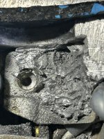
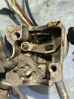
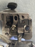
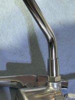
Well this was fun. A previous owner stripped the mirror threads in the switch housing. Creatively they attempted to epoxy the mirror in place from the inside out. Looks like they may have even tried to use a little fibreglas (or maybe toilet paper, who knows?) for reinforcement.
I dismantled everything, very carefully dremelled and picked all of the old epoxy out, gave it a bath in the Ultrasonic, bored out the old hole and put in a helicoil and now it's ready for action again (I am out of grey sheathing material so grey E-tape will have to do until my next order with Sparck Moto.)
IMG_0340.jpegIMG_0333.jpegIMG_0379.jpegIMG_0380.jpeg
 
I'm hoping there might be an S90 owner who spots this and can help? I've tried posted to the S90 FB group but for some reason I can't get it to post the group. (I hate FB)

The question is this...
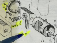
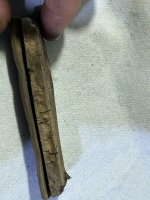
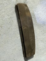
Part 14, PACKING CLEANER, part 17235-028-000, where exactly does it fit? I don't seem to have a photo from disassembly a year ago and I can't work it out. Mine is degraded and I can't seem to find a replacement but I'm not even sure what it's function is. If someone had a photo of it installed on a bike that would be most helpful.
Thanks
IMG_0368.jpeg IMG_0367.jpeg IMG_0366.jpeg
 
Last edited by a moderator:
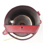
Wish I could be of more help but mine is the earlier model with the different air filter. It looks like it would seal one end or the other of the filter housing caps to me but without hands on hard to tell. Would it it fit in the area marked in this photo from EBay?

s-l1600.jpg
 
Last edited:
I was looking at this a few minutes ago and wasn't sure either, it's been far too long since my S90 in '69 to remember. I was thinking the slot/groove in the rubber sat over that folded edge above your arrow but it is definitely hard to tell without having the pieces in hand.
 
Does it fit into the slot opening and when that part is installed act as a cushion against an area that it abuts or attaches to?
 
Last edited:
I honestly think it acts as a dust seal to prevent dust and debris from getting into the end cap area. Tried to find an ebay listing with the whole assembly to look at but never saw that piece.
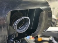
 
I honestly think it acts as a dust seal to prevent dust and debris from getting into the end cap area. Tried to find an ebay listing with the whole assembly to look at but never saw that piece.
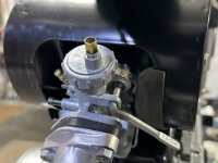
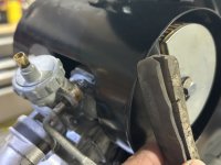
I would tend to agree but I can't find a spot that it would fit and serve that function. If I try to find a spot for that match the orientation in the parts diagram it would go here but I don't think that would do anything at all and probable wouldn't stay in place for long at all.
IMG_0384.jpeg
IMG_0382.jpeg
Unless I'm missing something, I can't really see how it would fit between the airbox and the end cap or what it would do? Again, I'm assuming that the part is installed on the bike in a similar orientation to the diagram? Really need to find a photo somehow. I've tried several times to post on an S90 FB group but for some reason my posts are being blocked.
IMG_0383.jpeg
 
Quick update. I just a got a message from the S90 FB group admin explaining why my post had been blocked...
"I had a parameter set that declined new members or posts with profiles with no photos but I’ve since lifted it. We’re not really a dating page. lol" My post is now on that group's page so hopefully somebody there chimes in with help and I will update here when/if that happens.
 
Been a while since I've updated this thread...
-I was never able to find a logical location for the rubber part discussed previously. For now, it sits in a drawer.
-Ordered supplies from Venhill and now have a good set of cables.
-This past weekend repainted fenders and tank. They turned out ok. Not great but ok. Some wet sanding is in order.

Installed rear fender and tail/signal lights. Kind of a weird scenario and I'm hoping somebody can shed some light (pun intended) on it for me. Quick background. I upgraded all bulbs on the bike to LED's except the headlight, for which I have been unable to find an LED replacement for.
Headlight and signal lights work as they should, all sharing a common ground wire connected to the battery. The tail light/brake light will work but not when connected to that common ground wire. The only way to get the tail light to work at all is to run a ground a dedicated ground wire directly to the battery. I have used a lead with alligator clips to try everything else and there is no other grounded point on the bike that I can use that will allow the tail light to work. I have tried multiple points all with confirmed continuity to ground but it just doesn't work. Now, this isn't an insurmountable problem as I can easily run a dedicated ground to the battery but I would love to know why this is happening? Of course my wiring would be simplified if I could just use the common ground but I'm equally prepared to just add a ground directly from the tail light to the battery.

Other than that, I'm hoping to plumb the bike and take it for a test ride this week.

Cheers
 
If I'm correctly understanding what you've said, it sounds like the rear fender doesn't have a good clean ground to the frame. Or the battery needs an additional ground wire to the frame.
 
You are correct. There isn't a good ground from the light socket to the frame but I anticipated that and ran a ground wire direct from the bulb socket.

There is a common ground wire that runs directly from the headlight to the battery and collects the ground for a few other things along the way (rectifier, signal switch, high beam indicator) I added the ground for the tail light to this with no success, despite it being a known good ground. All other lights work as they should except the tail light, however, when I unplug everything else from this very same ground wire and leave only the tail light connected it works.

So, the tail light works with this ground until I plug the headlight and signals back in and then it stops working.

As I've said, I can run the tail light directly to the battery and everything works so I have a solution but not an understanding of what's happening.
 
You are correct. There isn't a good ground from the light socket to the frame but I anticipated that and ran a ground wire direct from the bulb socket.

There is a common ground wire that runs directly from the headlight to the battery and collects the ground for a few other things along the way (rectifier, signal switch, high beam indicator) I added the ground for the tail light to this with no success, despite it being a known good ground. All other lights work as they should except the tail light, however, when I unplug everything else from this very same ground wire and leave only the tail light connected it works.

So, the tail light works with this ground until I plug the headlight and signals back in and then it stops working.

As I've said, I can run the tail light directly to the battery and everything works so I have a solution but not an understanding of what's happening.
Did you take the bulb out of the socket and examine the socket? Sometimes the inside of the socket gets corroded a little and/or the lead contacts on the bakelite plate, which only has a small locating tab to keep it properly oriented in the socket, can cause trouble.
 
Did you take the bulb out of the socket and examine the socket? Sometimes the inside of the socket gets corroded a little and/or the lead contacts on the bakelite plate, which only has a small locating tab to keep it properly oriented in the socket, can cause trouble.
On my early S90's (1965 and 1966) I think the socket was grounded to the tail light/license plate bracket. The bracket was grounded to the fender (bare area on both the bracket and the fender. The fender grounded to the frame at 4 (if I recall correctly) attachment points. Lots of places for this ground circuit to fail. At least that's what I THINK I remember.
 
Did you take the bulb out of the socket and examine the socket? Sometimes the inside of the socket gets corroded a little and/or the lead contacts on the bakelite plate, which only has a small locating tab to keep it properly oriented in the socket, can cause trouble.
I completely swapped out the old wires for new, soldering to the original contact points. Bulb is fine in the socket and the socket is clean. It's possible that I'm not communicating the scenario properly. The bulb and socket work. I have established a good ground. Everything works just fine as long as it isn't connected to the common ground that connects the headlight to the battery.

On my early S90's (1965 and 1966) I think the socket was grounded to the tail light/license plate bracket. The bracket was grounded to the fender (bare area on both the bracket and the fender. The fender grounded to the frame at 4 (if I recall correctly) attachment points. Lots of places for this ground circuit to fail. At least that's what I THINK I remember.
That's all correct. Because I have a freshly painted fender and newly powder coated frame and tail light bracket I didn't even bother trying to establish a ground using these parts. I assembled a ground wire that I attached directly to the back of the socket between the socket and the bracket. It works perfectly and is routed with all the other wires.
At this point I've found a work around to the challenge and am not spending any more energy on this. I will run said ground wire from the tail light right to the battery. No further action required at this point but I'm still curious to solve the mystery some day.
 
LED's don't dim under poor voltage they just won't light. If that common ground is not really very good, it may work for the stuff up front but when adding the tail light it drops voltage then nothing works.
Looking at the wiring diagram there is minimal grounding further back or maybe none in your case and you are only grounding through the speedo bracket and forks. I would add an extra ground wire from that forward ground cluster all the way back to the battery and attach the tailight ground there too. As LDR says, you can't have too many grounds. The negative return path needs to be as robust as positive feeds, especially with LEDs.
 
Ballbearian, when do you find time to dream the dreams you speak of? Your posts seem to come at what I can only assume are the wee hours of the day in Maryland!! (I'm an early riser too)

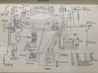
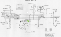
For reference, the wiring diagram below most closely resembles my bike with a few minor differences.

Anyhow thanks for chiming in and you and I are definitely thinking the same. A good point about LED's not dimming.

I am making progress but the plot has thickened a bit. After establishing a ground wire directly from the tail light socket to the battery yesterday it works but now it seems that gremlin has moved elsewhere. My signal lights aren't working properly. Aaargh, but it's progress. So out comes the multimeter and I started checking circuits to see what's up and by chance I find something that seems like trouble. I have continuity between the frame and the switched power to the ignition coil. With combination switch turned on, of course that continuity extends throughout the entire switched power circuit. Presumably this positive current in the frame is messing with the ground for the signals.

My conclusion is that I have a problem with the ignition coil? I'm hoping one of the veterans here can chime in for me. It's a real pain to get at the coil on this bike as it's hidden up on the motor inside of the frame. Getting to it will require dropping the motor.


Screenshot 2025-04-18 at 5.30.58 AM.png
 
-would I be correct in assuming that the coil is cooked and shorting to the frame? I don't know the inner workings of a coil well enough to do anything more than guess.

https://www.amazon.ca/MOTOALL-Ignition-Replace-Honda-CB100/dp/B09YD5K555

-If that's the case would this do the job? I have a bit of a time crunch right now and I can have this here tomorrow for a pretty low cost, understanding that I may need to improvise the mounting as it may not be a direct bolt-on fit.
 
I think you're on the right track - although I'm not certain a cooked coil would ground to the frame - I'd be looking at that 6 pin connector as a real likely culprit. Just based on the diagram I could see someone crossing up the ground and switched wires there.
 
Back
Top Bottom