
Boomer343
Veteran Member
https://www.vintagehondatwins.com/forums/index.php?threads/4484
Thanks to Connor1 and Bob Foist from the linked thread I set out to do this modification. Their numbers gave me a starting point and proof it was a doable and desirable modification.
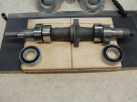
NTN 6004 ball bearings were used, the side covers will be removed before final assembly. 20mm x 42mm x 12mm are the bearings stated dimensions.
The cam has to be machined down to 20mm from its original 22mm.
Note .... Actual measurements are different, the inner diameter of the bearing was measured with a bore gauge and micrometer. Outer diameter of cam was turned to match but give a slip fit as measured with a micrometer.
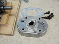
I changed the mounting screws to allen head fasteners with washers. I also used a torque wrench set to 75 inch/pounds to tighten the fasteners.
The gaskets are new and their thickness needs to be taken into consideration. Mine measured .57 mm
For those just wanting the numbers this is what my next one will use.
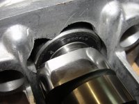
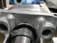
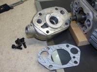
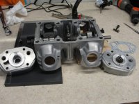
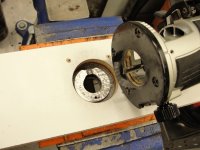
Points side: Leave 6mm as measured from machined rub face. On cam cover leave 5mm lip to be sized to approx 4mm. Dish the lip to give clearance to the bearing, leave an outer ring.
Tach side : Leave 7mm as measured from the machined rub face. On cam cover leave 5mm lip to be sized to approx 4mm. Dish the lip to give clearance to the bearing leave an outer ring.
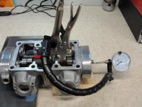
End play to be adjusted to .005" .... sorry for the measurement cross over, my dial indicator is Imperial. I was able to get .006" which could be changed by choosing a thinner gasket.
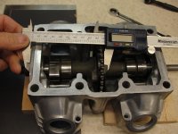
Start on one side and centre the cam gear in the case, measure only from the outside machined surfaces of the case. Size the lip on the cam cover to achieve the cam gear being centred.
Complete the other side to achieve the desired end play. The bearings twist easily and can give false readings. I found moving the bearing on the shaft slightly before each test gave the best results.
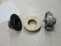
I made a mistake on the points side cutting the cam to 5.5 mm and then doubling down by cutting too much off the cam cover lip. A shim was required.
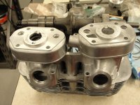
Pictures following.
Thanks to Connor1 and Bob Foist from the linked thread I set out to do this modification. Their numbers gave me a starting point and proof it was a doable and desirable modification.
NTN 6004 ball bearings were used, the side covers will be removed before final assembly. 20mm x 42mm x 12mm are the bearings stated dimensions.
The cam has to be machined down to 20mm from its original 22mm.
Note .... Actual measurements are different, the inner diameter of the bearing was measured with a bore gauge and micrometer. Outer diameter of cam was turned to match but give a slip fit as measured with a micrometer.
I changed the mounting screws to allen head fasteners with washers. I also used a torque wrench set to 75 inch/pounds to tighten the fasteners.
The gaskets are new and their thickness needs to be taken into consideration. Mine measured .57 mm
For those just wanting the numbers this is what my next one will use.
Points side: Leave 6mm as measured from machined rub face. On cam cover leave 5mm lip to be sized to approx 4mm. Dish the lip to give clearance to the bearing, leave an outer ring.
Tach side : Leave 7mm as measured from the machined rub face. On cam cover leave 5mm lip to be sized to approx 4mm. Dish the lip to give clearance to the bearing leave an outer ring.
End play to be adjusted to .005" .... sorry for the measurement cross over, my dial indicator is Imperial. I was able to get .006" which could be changed by choosing a thinner gasket.
Start on one side and centre the cam gear in the case, measure only from the outside machined surfaces of the case. Size the lip on the cam cover to achieve the cam gear being centred.
Complete the other side to achieve the desired end play. The bearings twist easily and can give false readings. I found moving the bearing on the shaft slightly before each test gave the best results.
I made a mistake on the points side cutting the cam to 5.5 mm and then doubling down by cutting too much off the cam cover lip. A shim was required.
Pictures following.