• Don't overlook our Welcome Package, it contains many links to important and helpful information about functions at VHT like posting pictures and sending PMs (private messages), as well as finding the parts you need.

    AD

DOHC 450/500T head assembly

ancientdad

Administrator
Staff member
Joined
May 22, 2020
Total Posts
24,749
Total likes
2,796
Location
Nature Coast, FL
Since the 450 and 500T have the only cylinder head with torsion bar valve springs, it is one of the more unique engines to rebuild among our vintage Honda twins. Since words don't often tell the full story of how to assemble the head, and particularly since there are many videos out there showing anything from incorrect to horribly incorrect ways to both disassemble and reassemble the head, I've tried to put together something to help. Credit goes to HT member gizwiz for most of the pictures in this thread, but I have extensively clarified the description of the process to give better details. The following assumes the head is already disassembled and all parts are inspected, clean and ready to install.

When replacing valve guide seals, be careful tightening the 6mm seal retainer bolt. Use good "feel" and tighten cautiously to avoid stripping the threads in the head as the bolt is short. [Note: if you're building a Bomber (4 speed) engine, the valve stem seals may be different and this step does not describe that design]

bEQ3wgA.jpg


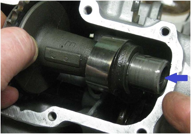
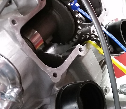
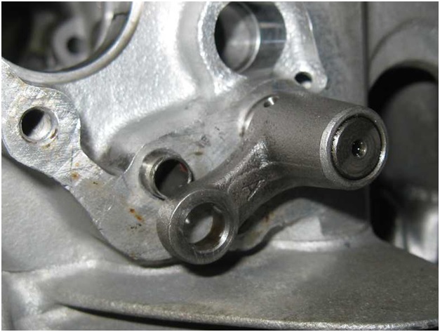
When installing the torsion bars note that there are 2 different types, A and B. The As go in the right intake and the left exhaust, the Bs go in the left intake and right exhaust. This picture shows the right intake. Slip the splined tube into the head and through the "fork" that goes under the keeper cup and lifts the valve closed. They are splined such that they can only be installed one way.

eF8OooR.jpg


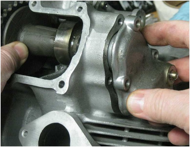
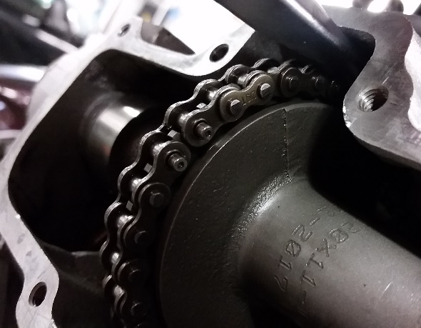
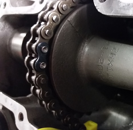
This shows the general position of the fork on the torsion bar tube

8JC8qFt.jpg


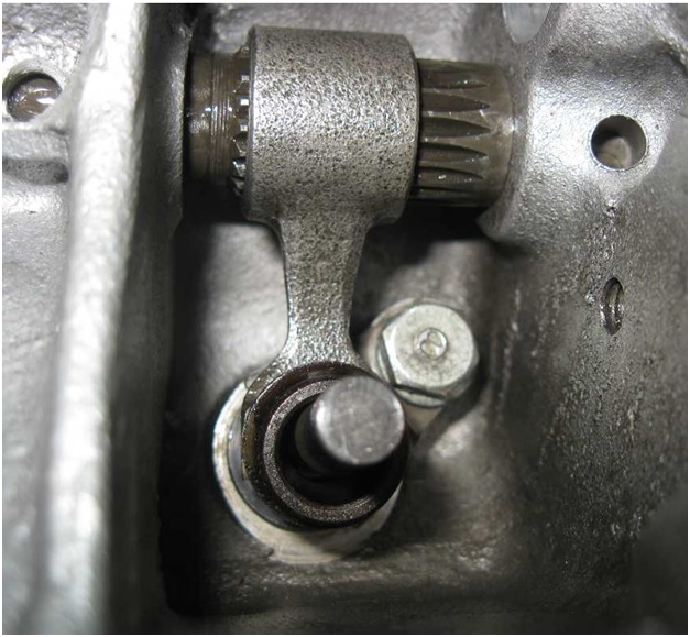
Slip the valve into the head and up through the fork

oYVge93.jpg


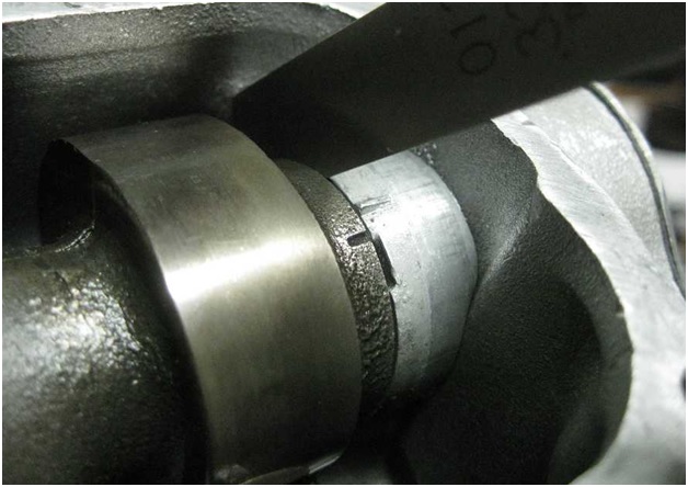
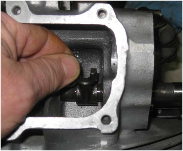
Leave the torsion bar off the dowel pin so the fork sits below the top of the valve stem

N2EdlH9.jpg


Drop the valve retainer cup over the valve stem

zDBvZqg.jpg


Put a little bit of grease on one of the valve cotters and place it on the valve stem in the indented section of the top of the stem

jCtf4WX.jpg


Slip the other cotter in and lift the torsion bar to pull the retainer cup up and over both cotters, and make sure both are seated in the valve stem. They will sit flat and equal height in the retainer cup if properly engaged in the stem.

TPJvPnY.jpg


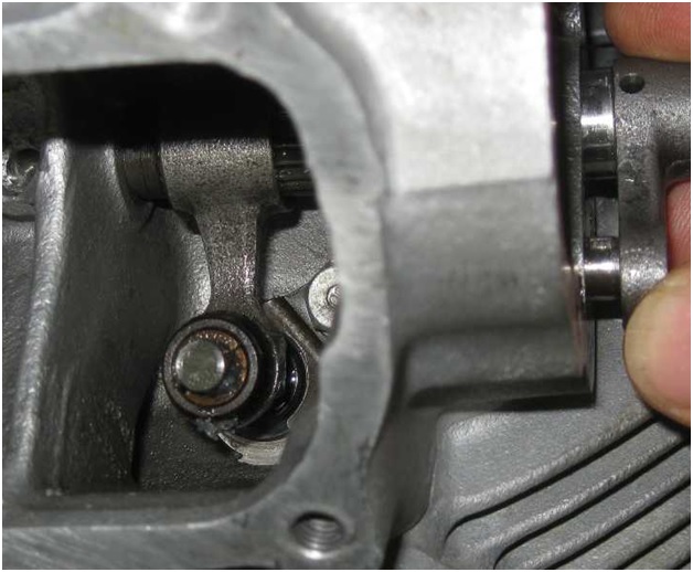
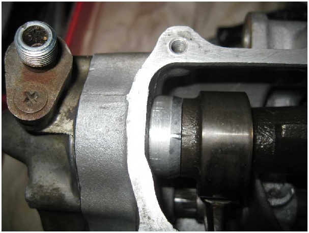
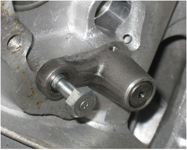
Using a 14mm open-end wrench, lift the torsion bar by rotating the end until it lines up with the dowel pin and tap it over the dowel pin.

WkNUm8t.jpg


And then put the bolt in

gSYAOrP.jpg
 
Last edited:
Now you can put the follower in place above the valve and slip the eccentric follower shaft through its hole in the head and into the follower

TbwJpau.jpg


With the eccentric shaft all the way in, the tip of the follower will sit right on top of the valve stem. Watch the height of the follower and rotate the eccentric shaft until the follower pad (where the cam lobe rides) is at the lowest point to create the maximum clearance for camshaft installation.

OB9BUAy.jpg


Before moving on to the camshafts, it's time to take care of one other thing that won't be accessible once the cams are installed. It's something that doesn't often need to be disassembled for cleanup or maintenance reasons during a rebuild but if you've removed the top guide sprocket (#10) for any reason, now is the time to re-install it. I don't always remove it as it's rare to see any problems with it, or with the o-ring seal on that shaft leaking either, but don't forget to do it at this point or at least one of the cams will have to be removed to put the guide sprocket back in later.

top guide roller.jpg

Once the same parts as above are installed on the other side of the head, you can install the intake camshaft. Rotate the cam so that both lobes point outwards away from the followers so you'll have clearance to install the cam bearing covers without using force. Note that the end of the intake cam with the oil restrictor in it, indicated by the blue arrow, goes to the right side of the head (engine's right, as if sitting on the bike)

i9YciwE.jpg


With the cam slipped into the head and the follower shafts rotated to their loosest point, the bearing covers can go on. Wiggle the parts around until they align and they slide in easily. If you have to force it, something is wrong.

Lu10TK6.jpg


The axial (end) play of the camshafts should be between 0.05 and 0.35mm (.002" and .014"). Once you tighten the cam bearing cover screws (with new gaskets) you'll be able to measure the clearance with a feeler gauge. Shims come in 0.1mm and 0.2mm thicknesses to keep cam end play in spec. The intake cam can be rotated close to the alignment position needed to set the cam timing once the intake side assembly is complete, and the marks are visible in this picture.

fTUUKrX.jpg


Repeat the above steps to assemble the exhaust cam in the head. Note that the tach drive has to engage correctly in the end of the exhaust cam for the bearing cover to go on fully and not cause damage. After the exhaust cam is slipped into the head, it's easier to put the tach drive bearing cover on first and rotate the cam slightly until you feel the tach drive drop into place in the end of the cam, at which point the cam will sit flush against the inside end of the cam bearing cover.

Note that the timing mark on the exhaust cam is visible in the picture below, aligned with the index mark on the tach drive side cam bearing cap. It's important to know that some cams have "ghost" marks on them in the same area that can look like timing marks, but are not. If you have ANY doubt that the mark you see is the real timing mark, DO NOT assemble the top end before taking a picture of it and posting it in your rebuild thread so it can be verified.

When installing the points side cam bearing cover, use a little bit of oil on the inside edge of the seal behind the points and rotate the cam or the cover as you gently slip it over the bearing surface to avoid damaging the seal.

OEPi9r8.jpg


Once the head is fully assembled (but before you rotate the exhaust cam to the timing mark) you'll want to check for minimum valve clearance. If you've had any head work done, you'll want to check this first in case the seats were cut too deeply and the valve stems need to be tipped for proper range of available valve adjustment clearance.

Once the cams are in the head and the bearing covers on and screwed down, then you align the timing mark on the exhaust cam using a flat screwdriver against the front edge of the valve cover opening, levering the sprocket teeth to rotate the cam so the timing mark aligns with the index mark on the tach side cam bearing cover. One exhaust valve will be slightly open. It's safe to do this ONLY if all the cam chain guides are already installed in the head because the forward guide sprocket will elevate the front of the head and the exhaust valve that partially opens will not contact anything.

You can leave the intake cam alone except to rotate it with your hand until you see the timing mark come near the index mark on the right side intake cam bearing as seen in the picture above (same side as the tach drive, the bike's right as sitting on it). The intake side will be a tooth or two from opening a valve when the timing mark is near but it won't stay there like the exhaust does because it's only just beginning to open the valve.

Now the head is ready to slip onto the cylinder studs. Turn the crankshaft to LT on the alternator rotor and use something to keep it from rotating past due to the alternator rotor magnets' pull (I like to use a long 6mm bolt screwed into one of the 3 cover screw holes and lean a 14mm wrench or ratchet/socket combo on the rotor bolt against it). As you lower the head down on the studs, you can use a block of wood to support it above the mating surface of the cylinders to give yourself room to slip the cam chain up into the intake and exhaust valve cover openings in the head. You'll want more cam chain length in the front of the engine as you slip the head on the studs because the next step is to thread the chain through the exhaust side, under the guide sprocket in the middle top of the head, then across into the intake side so you can lever the intake cam into position and connect the chain with the master link. (yes, that picture shows the work being done in the frame - it CAN be done but only if done correctly). Use zip ties in the ends of the chain to give you something to use to thread the exhaust side of the chain through and to give you something to retrieve the chain if you drop it.

RgAu5zI.jpg


It's best to have the cam chain tensioner assembly pushed all the way back and locked in position for maximum cam chain slack, or just removed from the back of the cylinders. Be advised that rotating the engine with the tensioner removed can sometimes result is the chain slipping a tooth if the cam chain is not new.

eXfFE64.jpg


Intake cam rotated into position, both ends of the chain on the sprocket and the master link slipped in, then the pins staked in the picture below.

I3SOh30.jpg
 
Last edited:
Back
Top Bottom