Warming the Wiring in Winter
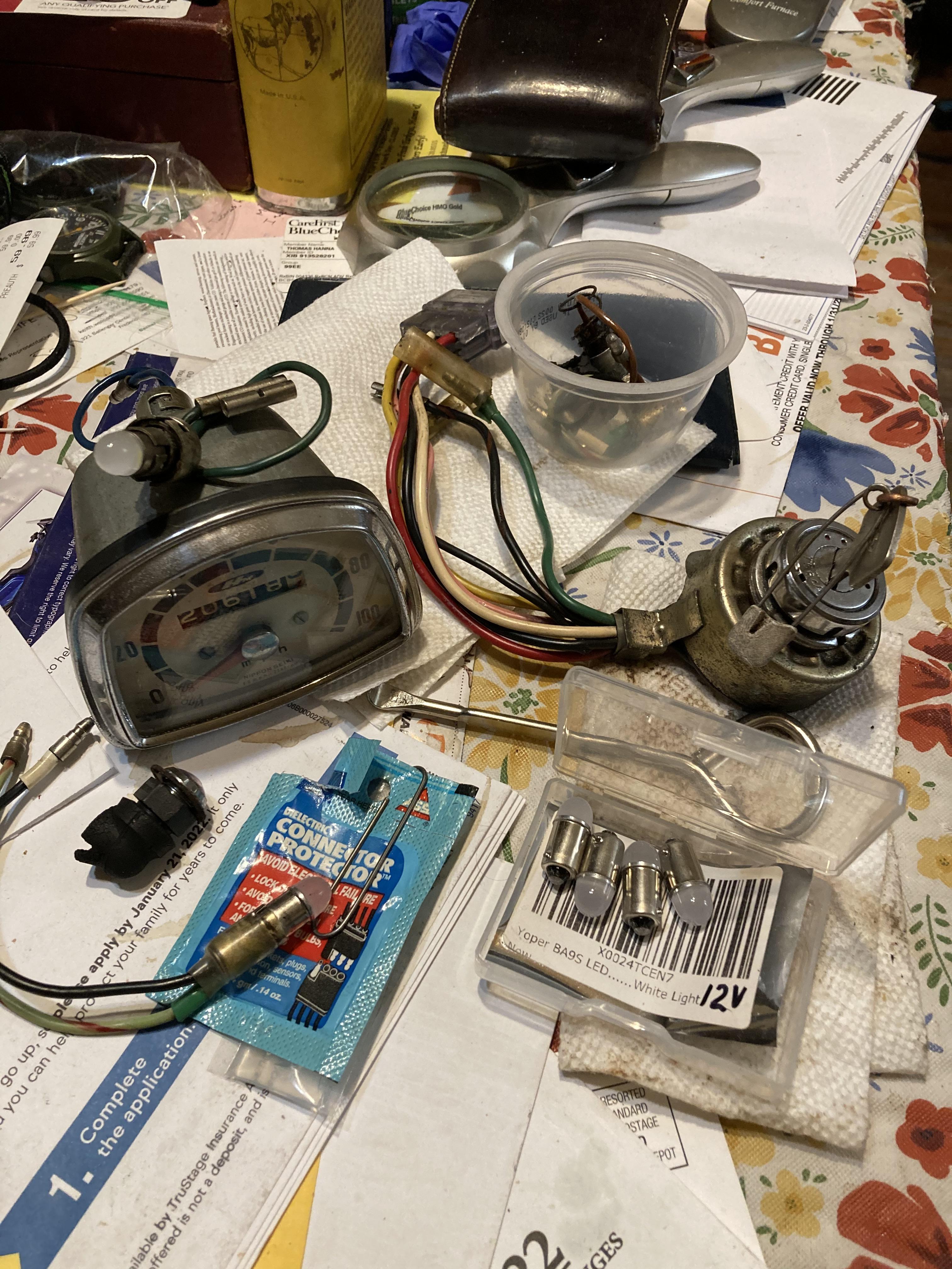
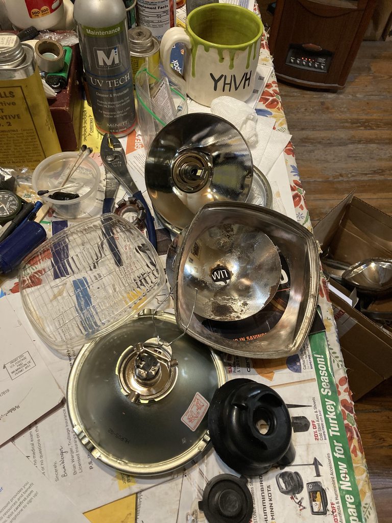
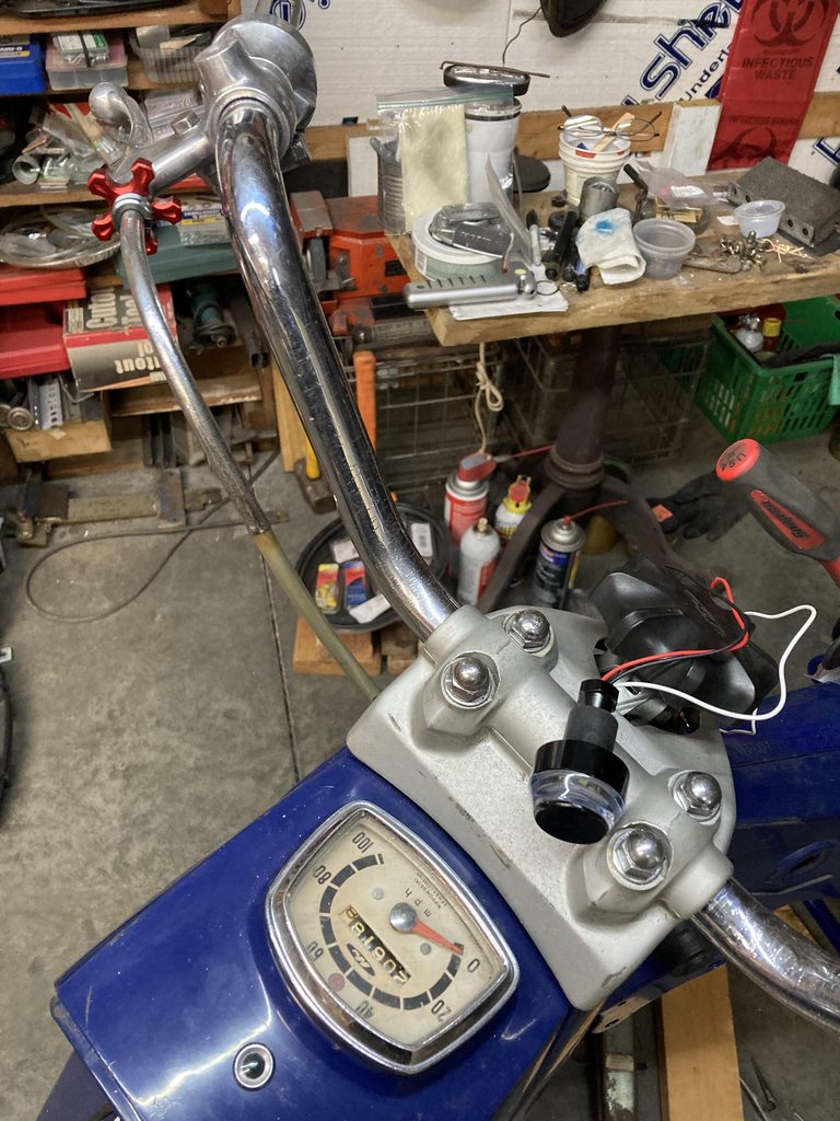
Temps above freezing let me warm the shop enough to get up from the cozy kitchen table cluttered with sub- assemblies like headlamp, handlebar switches, speedo and it's indicator lights. Every little thing on this bike is either rusted, bent or worn. I'm not complaining, it has kept my primary contact point warm. Cold, stiff wires are not very cooperative for re-installing the main harness. All contacts and connections cleaned, dielectric greased, and most soldering done. Sheathing repaired.
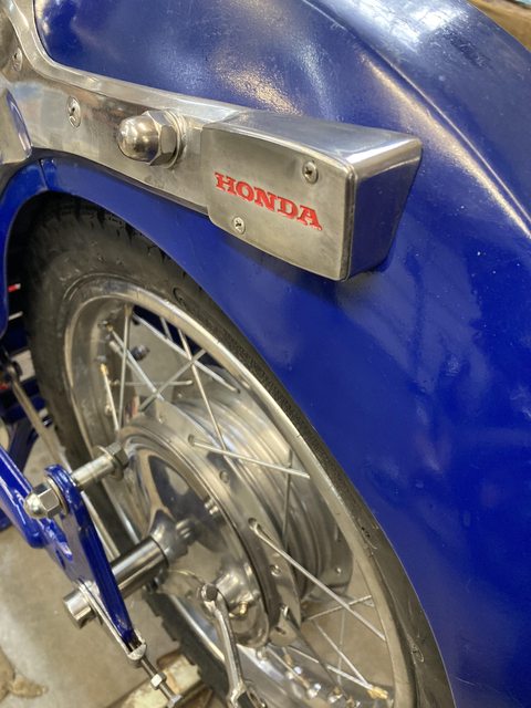
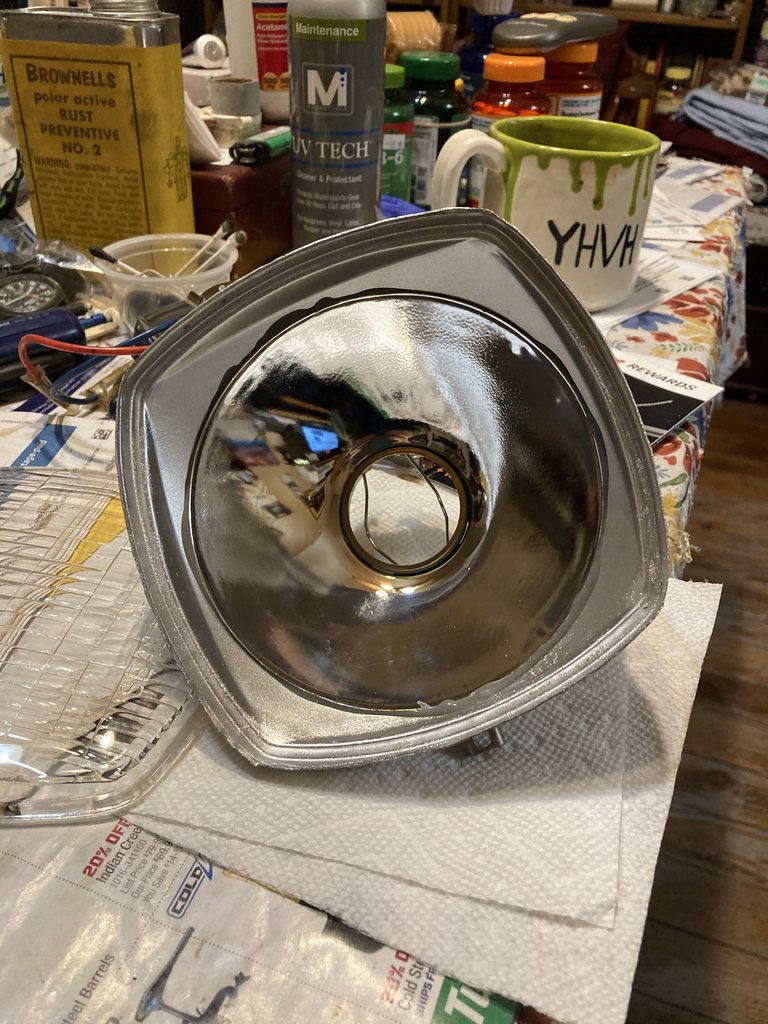
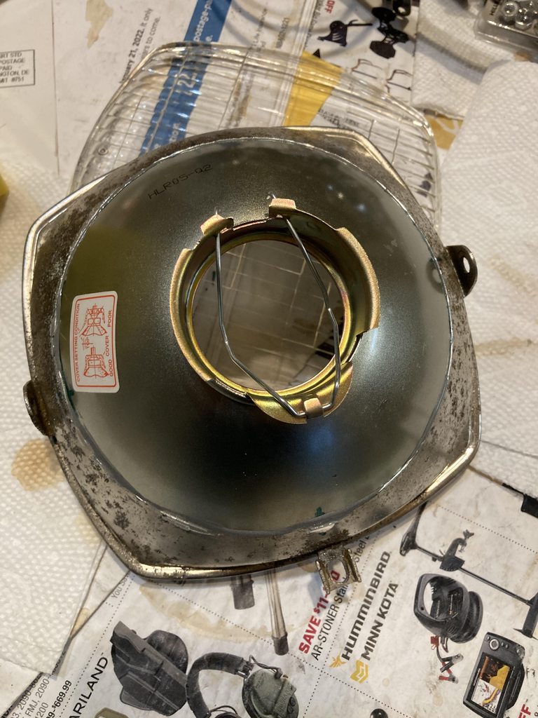
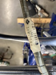
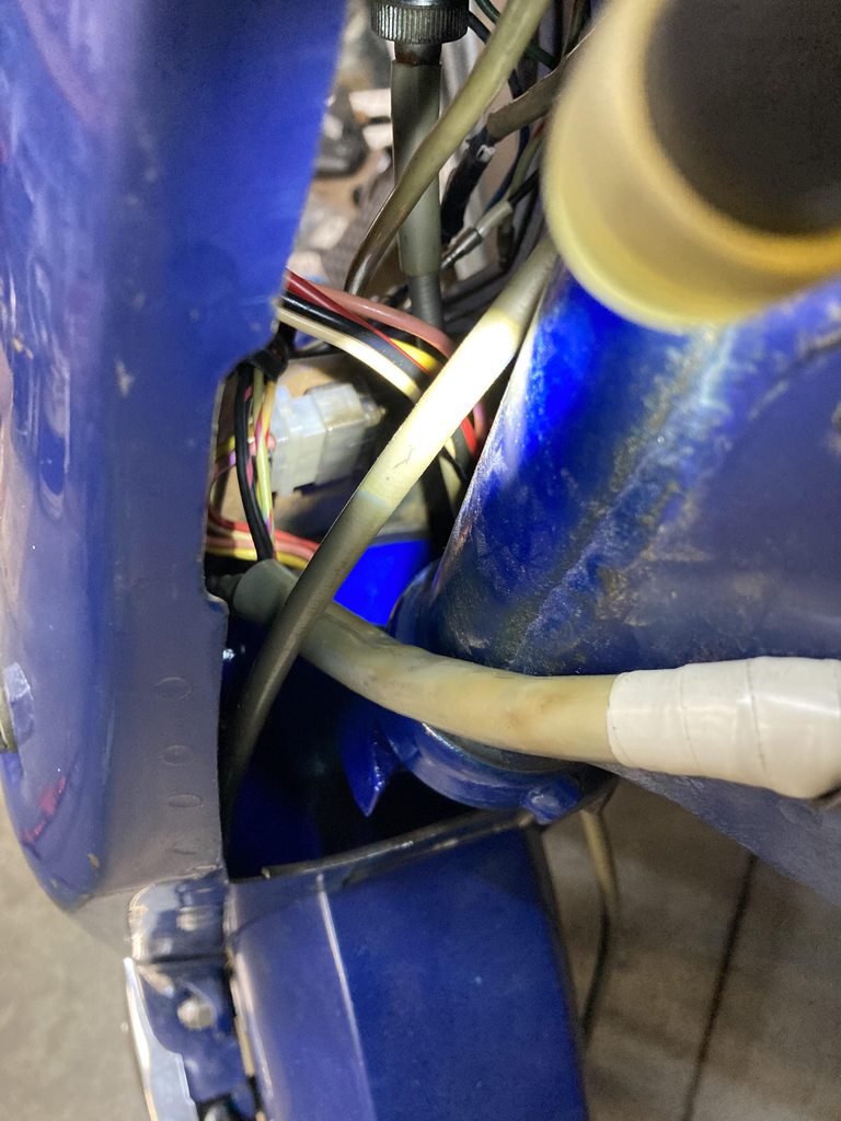
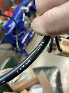
My early '64 has it's wiring harness sub contractor manufacture date tag of 1963. Besides a few frayed bullet connector conections, it was in good shape, beside the usual cracked sheathing at the steering area, which got a careful gray tape overwrap. The OEM wiring was pretty high quality materials and workmanship, IMO. I remembered, this time, there is a spring clip bracket inside the headlight bucket to hold the 6 pin connector block fixing the key switch to the harness.
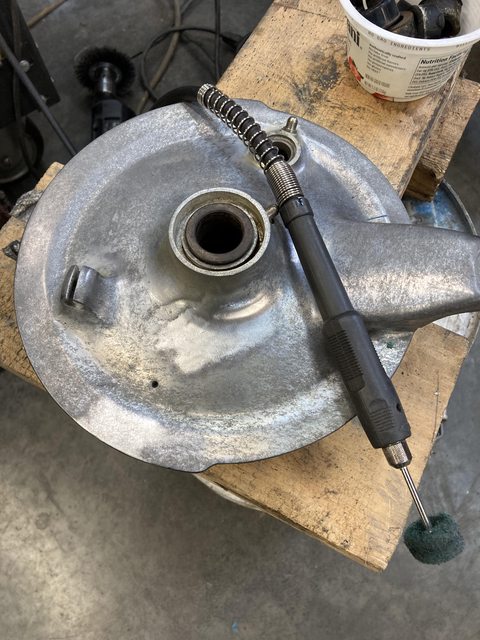
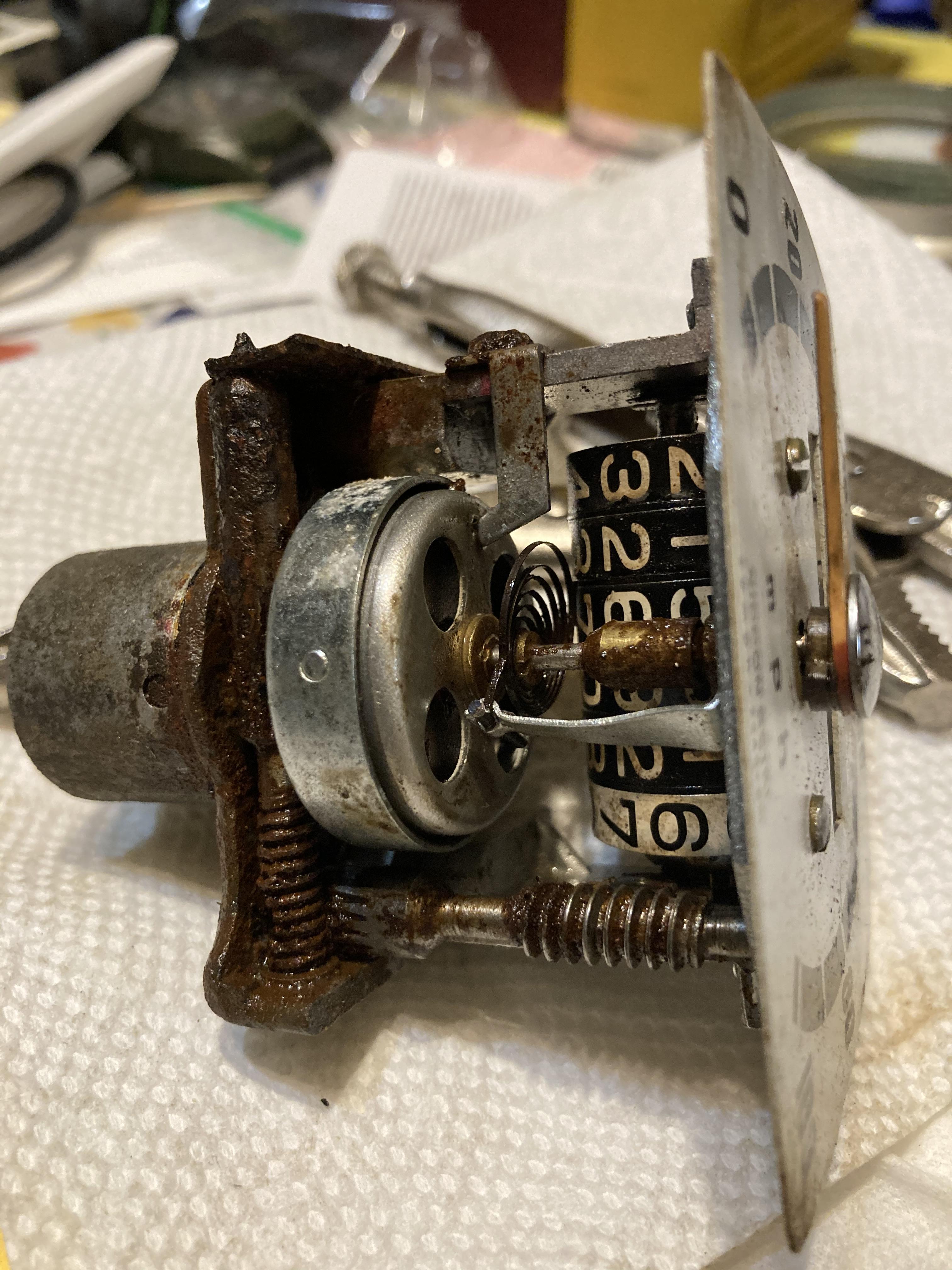
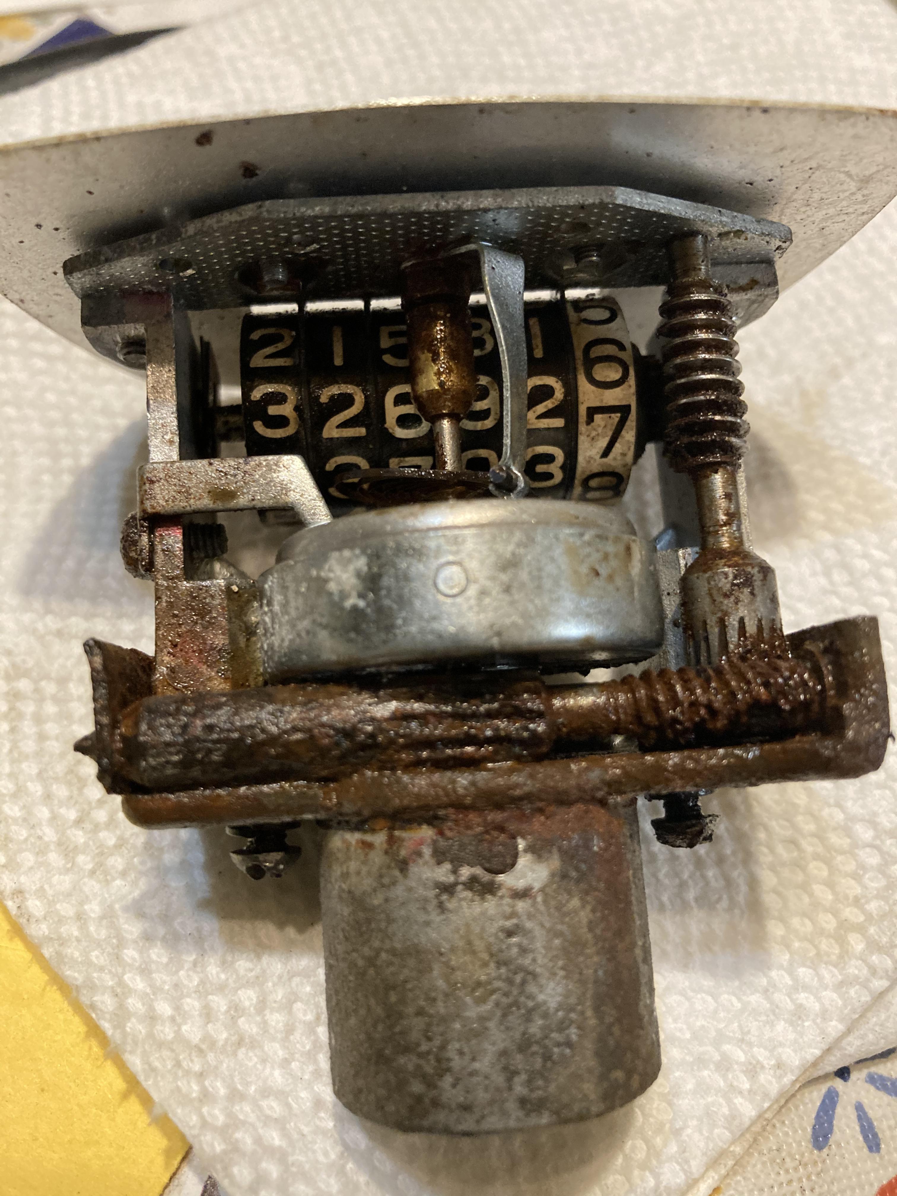
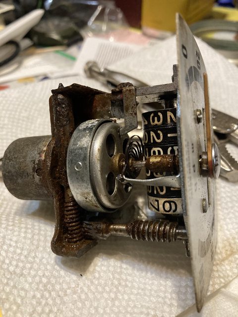
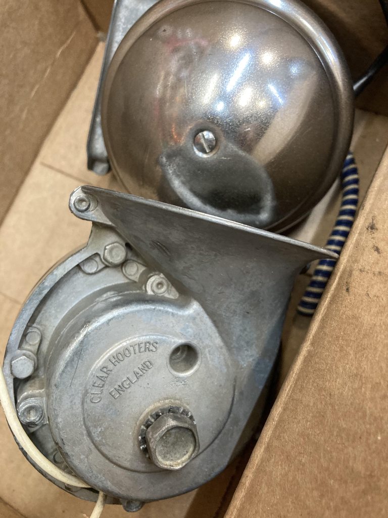
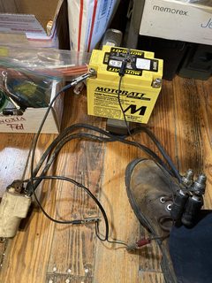
Even the starter solenoid got overhauled. The electromagnetic push rod inside should move free with your finger and clean up the fat flat contacts which are the copper bolt connections to the battery and starter cables. Goobers of dielectric grease on the contacts for sure. Original selenium rectifier was working but I had a new silicone unit ready and I want full charging capability. Also made a spot for a winker relay, which the bike never had. I'm still fooling with the coil.
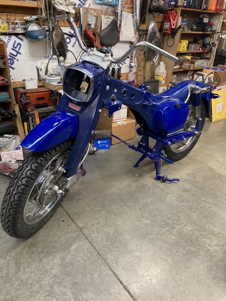
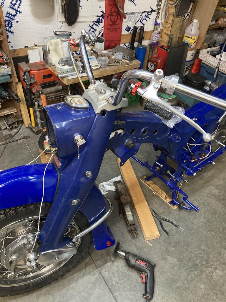
Pulling the control switches wiring through the handlebars is fun (this time I remembered to deburr the sharp edges of the handlebar wiring holes, especially at the bottom/center, where they always get cut) and you can still see the pull wires I used to get them through, because.......
I'm putting the winkers on the ends of the bars
They don't mess with the looks of a Dream like most add-ons do. Not as bright and not so noticeable in daylight as separate mounted type but they are cool at night because they have a constant white running light (yellow blink) that is quite distinctive from the rear. Following my friend Charles's '65 on dark rural twisty roads is sweet cause I can see exactly his handlebar movements and and outline of his body positions.
They don't draw squat power and are cheap, so maybe put another set to the rear if I can find a way that blends with the Dream.
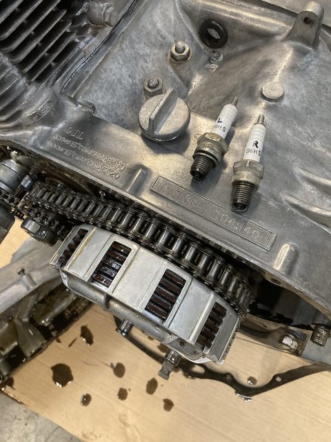
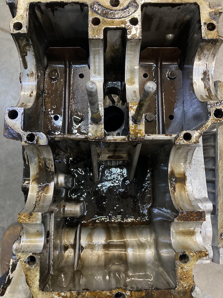
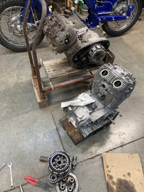
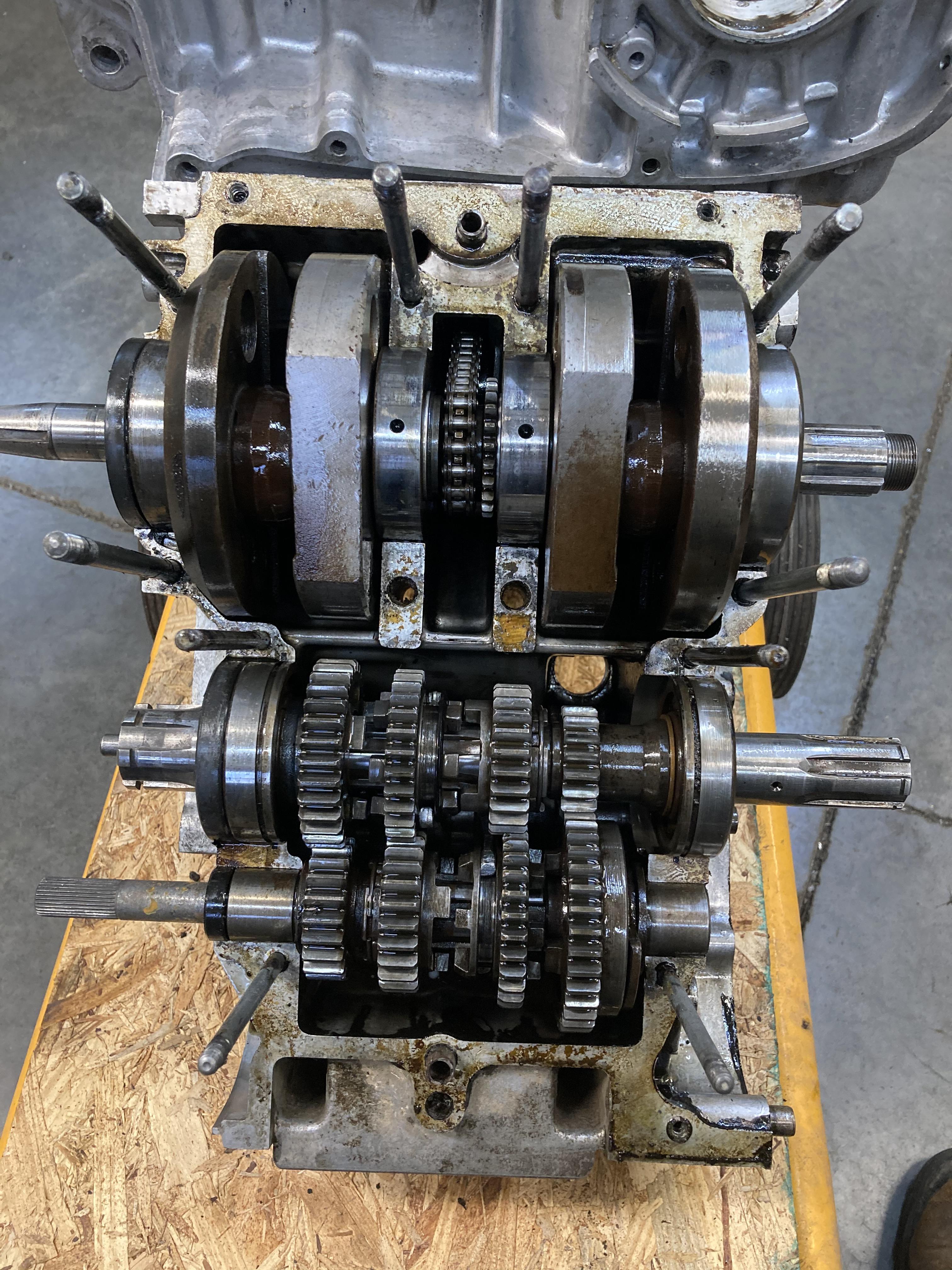
Sub assembly distractions are fun (to me), but I need to get cracking on the Honda Motor Company motor.


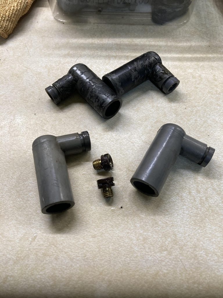
")