
Richard Pitman
Veteran Member
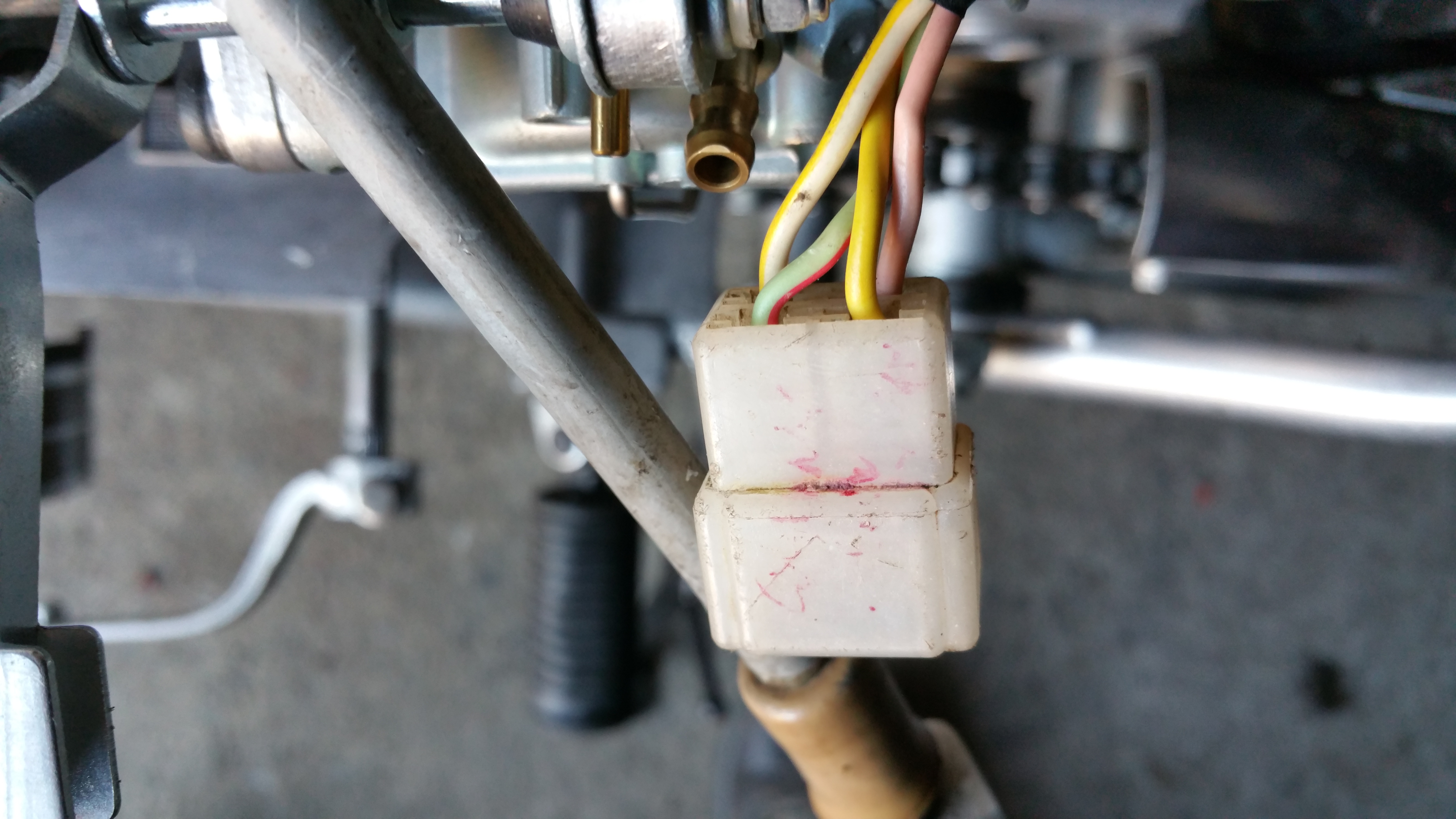
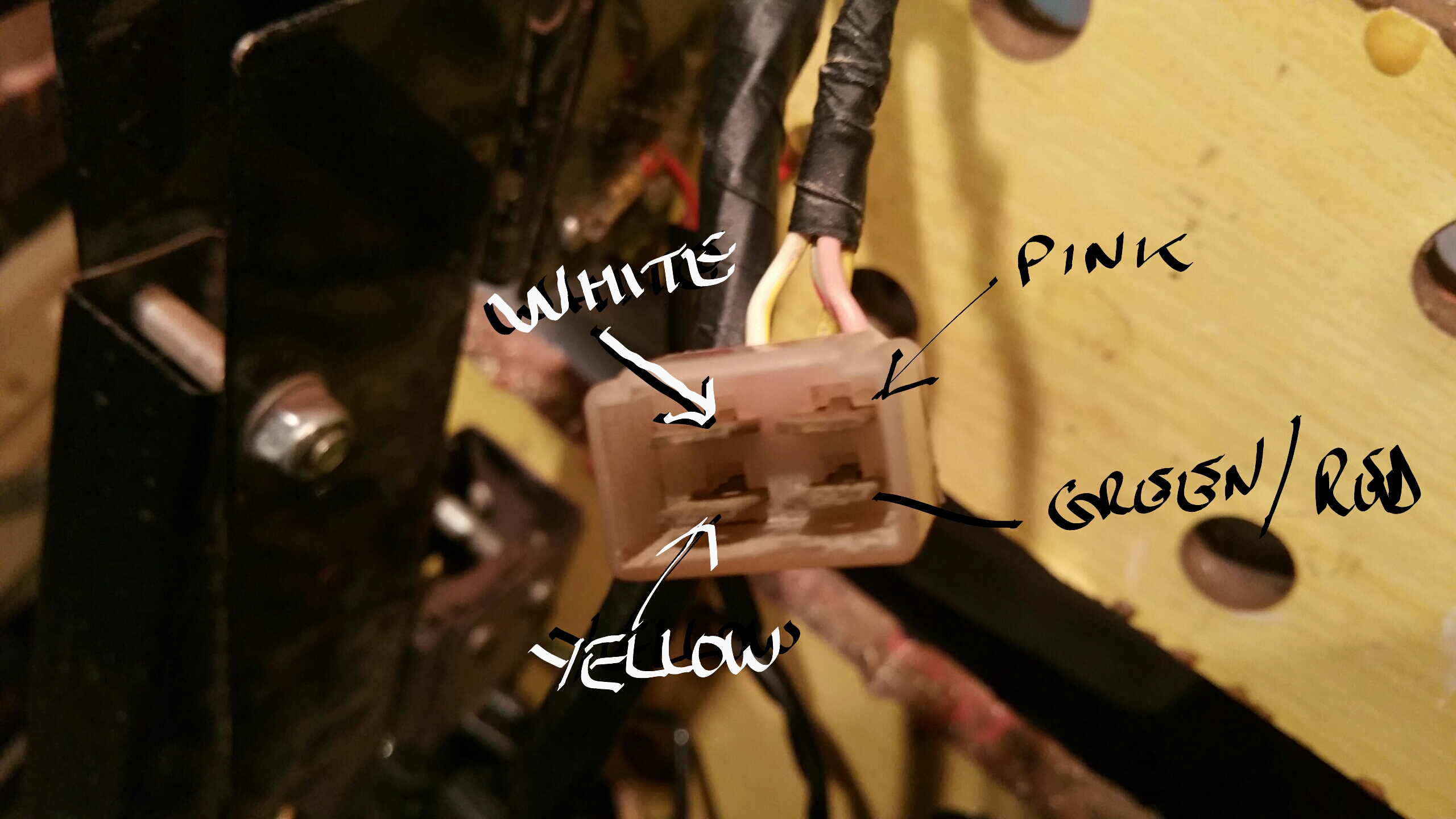
Four wires, one ( green with red stripe ) is for the neutral switch.
Other three should be yellow, white and pink. As standard, pink wire goes straight to rectifier, as does the yellow wire. White wire is switched ( or hard wired ) to the yellow wire for increased charging.
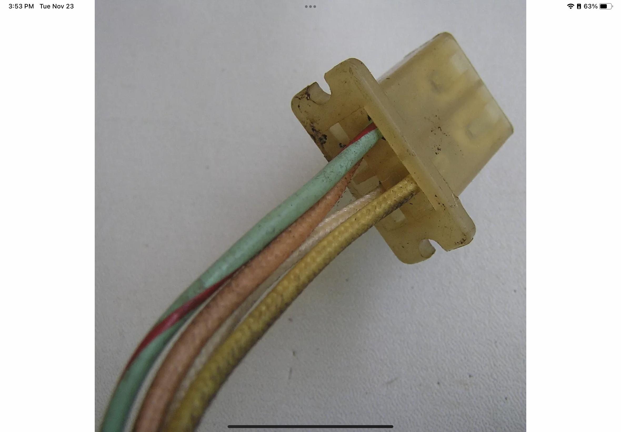
Problem arises when it's difficult to identify the wire colours at the stator.
No way of identifying which is which using a meter ?
Am I right in thinking that charging would work just as well if white wire was combined with the pink wire ?
But it wouldn't work if, for example, white wire went direct to rectifier, and the pink and yellow wires combined went to other connection on the ( four wire ) rectifier ?
( Which might explain why my CL360 stator conversion didn't work )
Other three should be yellow, white and pink. As standard, pink wire goes straight to rectifier, as does the yellow wire. White wire is switched ( or hard wired ) to the yellow wire for increased charging.
Problem arises when it's difficult to identify the wire colours at the stator.
No way of identifying which is which using a meter ?
Am I right in thinking that charging would work just as well if white wire was combined with the pink wire ?
But it wouldn't work if, for example, white wire went direct to rectifier, and the pink and yellow wires combined went to other connection on the ( four wire ) rectifier ?
( Which might explain why my CL360 stator conversion didn't work )