David
Member
Got my project truly underway today. First up is a top end rebuild.
Here is my first progress pic.

Here is my first progress pic.


Not likely wailing on it, but before taking time to read the FSM many just try to grab the little tang to pull the cover off, often even before they realize there's a screw into the end of the crankshaft holding the cover on the cup.Apparently in the past someone was wailing on the tabs and one broke.
You'll never notice a difference, probably half of them out there are like yours.Is this bad enough to throw things out of balance?


Rear axle for the bike pulls the rotor on this one. Even has a nice flat dish to smack with a hammer to pop it off.Looks like the Motion Pro 08-00015 fits your model. You can find several vendors online selling this product at varying prices. You will also need a tool to remove the rotor. Sometimes the axle is the same size and pitch and can be used - I'm not sure about the CB160.


Nice job!I did one for my CB450 which has the same lock nut. I used a 24mm socket that was on sale for $6. Took about 20~30 minutes with a dremel and cut off wheel. A little clean up with a file to finish it off.
View attachment 55644 View attachment 55645


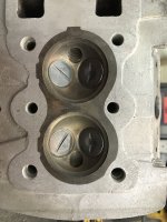
Hmmmm. That's .07MM. 1st OS is .25 Definitely borderline, IMO. However, since you're replacing pistons anyway, I'd do the 1st over at a minimum (or whatever set of pistons/rings are the easiest to come by), and just have a blank slateBack to the bore issue. I am replacing the pistons no matter what, the only question is standard or first oversize? At least, until I read page 129 of the FSM.
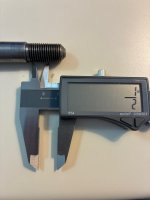
The manual says two things - bore size 50 mm and also 1.95 in. (in parentheses). Problem is, 50 mm is actually 1.9685 in. The ambiguity is actually more than 18 thou. The allowable clearance ranges from 0.004 to 0.008 in. My bores look pretty good and measured in with very little observable taper, at 1.972 in. or only 0.003 in. over the real value of 50 mm (1.9685 in.).
Just a bit of conundrum...
View attachment 55650
A machinist familiar with motorcycle engines would have no problem telling you what oversize you would need based on bore and wear limit specs from the FSM. Typically when pistons look galled like that, it usually requires an overbore.Back to the bore issue. I am replacing the pistons no matter what, the only question is standard or first oversize? At least, until I read page 129 of the FSM.
The manual says two things - bore size 50 mm and also 1.95 in. (in parentheses). Problem is, 50 mm is actually 1.9685 in. The ambiguity is actually more than 18 thou. The allowable clearance ranges from 0.004 to 0.008 in. My bores look pretty good and measured in with very little observable taper, at 1.972 in. or only 0.003 in. over the real value of 50 mm (1.9685 in.).
Just a bit of conundrum...

I'd love to take credit for an idea that I hadn't thought of, but that was Brad's (@boddy) great idea.Thanks Tom - I like the idea of bolting it my bench.
I'd send the head to Schumann Motor Works, he does excellent work on these vintage heads.Running into a snag with the reconditioning of the cylinder head.
I got everything disassembled nicely. The local machine shops however are not interested in measuring the small guide bores for clearance (likely don't have the tools). They are more inclined to replace the guides if they can 'feel play'. I cannot feel any play but at the small clearances published in the FSM, I doubt anyone could.
The speedometer indicates North of 13,200 miles. Should I just assume the guides need replacement and attempt to acquire them? Or is there any validity to the wiggle test for play?
Thanks in advance for suggestions...

 www.facebook.com
I've always felt it's better to not disturb the valve guides unless they really need changed. Changing the valve guide, more often than not, destroys the concentricity of the valve stem to the existing seat and the seats need re-cut to re-establish a proper valve seal. Taking metal off with a seat cutter sinks the valve farther into the head, go deep enough and you start to effect the flow characteristics of the head. Sinking the valve seat deeper also affects the installed height of the valve spring, affecting the closed and open spring pressure. Engines,such as the CB350/450 also run out of adjustment range when the valves are sunk deeper into the head. Also, if the person doing the guide change doesn't bother to clean the carbon build up off the lower end of the guide and drives the guide out with the head at room temperature it's possible to oversize the hole, losing the interference fit of the guide, in the head. Try a new, unworn valve in the guide,how does it fit? Any grooves on the sealing surface of the valves? If so they need to be tossed anyway.Running into a snag with the reconditioning of the cylinder head.
I got everything disassembled nicely. The local machine shops however are not interested in measuring the small guide bores for clearance (likely don't have the tools). They are more inclined to replace the guides if they can 'feel play'. I cannot feel any play but at the small clearances published in the FSM, I doubt anyone could.
The speedometer indicates North of 13,200 miles. Should I just assume the guides need replacement and attempt to acquire them? Or is there any validity to the wiggle test for play?
Thanks in advance for suggestions...

You don’t actually need to remove it. That crank is pressed together so the only way to clean the passages is long soaks of kerosene, brake cleaner, WD 40 and air. You can leave the rotor on there while doing all of that.Good to know Mike, thank you.
Tried both axles, not even close. Very fine pitch too

On mine an M16 bolt with air wrench will quickly remove the rotor. Sorry don’t remember the thread pitch. Pretty sure I picked it up at the local hardware store!Hello!
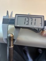
Finally getting around to splitting the cases (crank service on the menu). Had my M14 x 1.5 bolt at the ready.
Turn out the rotor is not from a CB160. the orphan in my engine is marked CB93L, and 5D00055. The threaded hole looks like M15 x 1.5, which I am quite sure is unobtanium.
Is this a common occurrence? Any suggestions how pull this puppy? I am considering using an M8 rotor bolt and stack of washers...
View attachment 56161